Compound spoil-retaining wall with holes for tundish and preparation process thereof

A slag retaining wall and tundish technology, which is applied in the field of composite tundish slag retaining wall with holes and preparation technology, can solve the problems of increasing the cost of the slag retaining wall, unable to meet the control cost of production units, etc., so as to increase the number of continuous drawing furnaces. , prolong the service life, reduce the effect of inclusions

Inactive Publication Date: 2009-11-18
SHANDONG IRON & STEEL CO LTD
View PDF3 Cites 10 Cited by
  • Summary
  • Abstract
  • Description
  • Claims
  • Application Information

AI Technical Summary

Problems solved by technology

The patented slag retaining wall adopts aluminum-magnesium spinel material as a whole, which is beneficial to improve the service life of the r

Method used


Image

  • Compound spoil-retaining wall with holes for tundish and preparation process thereof
  • Compound spoil-retaining wall with holes for tundish and preparation process thereof

Examples


Embodiment 1

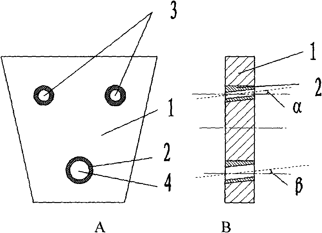
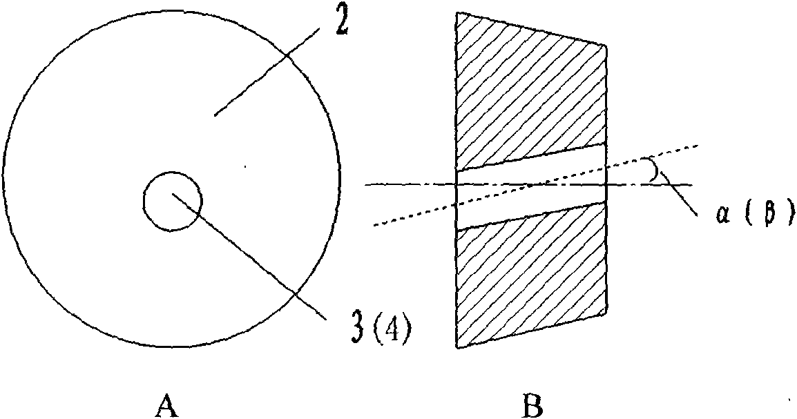
[0028] like figure 1 , figure 2 The composite slag retaining wall shown includes: a slag retaining wall body 1; an inlay 2; the inlay 2 is installed on the slag retaining wall body 1, and the inlay has flow steel holes 3 and 4 respectively.

[0029] The flow steel holes on the mosaic are distributed on the slag retaining wall in a triangular manner. The small flow steel holes are 3 through holes with a diameter of 70 mm. The angle between the center line of the hole and the center line of the vertical slag retaining wall body is 35°. The distance between the steel hole 3 and the bottom of the slag retaining wall is 300mm. The large flow steel hole 4 is a through hole with a diameter of 150 mm, and the angle between the center line of the hole and the center line of the vertical slag retaining wall body 1 is 35°. The distance between the large flow steel hole 4 and the bottom of the slag retaining wall is 200mm.

[0030] The number of inlays is set according to actual needs...

Embodiment 2

[0043] Others are the same as in Example 1, except that the small flow steel hole 3 is a through hole with a diameter of 50 mm, the angle between the center line of the hole and the center line of the vertical slag retaining wall body is 20°, and the small flow steel hole 3 and the slag retaining wall The distance from the bottom of the wall is 350mm. The large flow steel hole 4 is a through hole with a diameter of 100 mm, and the angle between the center line of the hole and the center line of the vertical slag retaining wall body 1 is 20°. The distance between Daliu steel hole 4 and the bottom of the slag retaining wall is 250mm

Embodiment 3

[0045]Others are the same as in Example 1, except that the small flow steel hole 3 is a through hole with a diameter of 100 mm, the angle between the center line of the hole and the center line of the vertical slag retaining wall body is 50°, and the small flow steel hole 3 and the slag retaining wall The distance from the bottom of the wall is 400mm. The large flow steel hole 4 is a through hole with a diameter of 200 mm, and the included angle between the center line of the hole and the center line of the vertical slag retaining wall body 1 is 50°. The distance between the large flow steel hole 4 and the bottom of the slag retaining wall is 300mm.


PUM

PropertyMeasurementUnit
Apertureaaaaaaaaaa
Apertureaaaaaaaaaa

Abstract

The invention relates to a compound spoil-retaining wall with holes for a tundish and a preparation process thereof. The compound spoil-retaining wall comprises a spoil-retaining wall body arranged on a proper position of the tundish and a mosaic; the mosaic is arranged on the spoil-retaining wall body; and the center of the mosaic is provided with steel flowing holes. The preparation process comprises the following steps: casting the spoil-retaining wall body by an aluminum magnesium or aluminum silicon or high aluminum or magnesium or magnesium aluminum material, and casting the mosaic by a corundum material; and curing the two casting materials with moulds after initial setting for 24h, demoulding, naturally curing for 12 to 24h, assembling and baking. The compound mosaic spoil-retaining wall for the tundish, on the basis of slightly increasing the cost of materials, further prolongs the service life of the steel flowing holes, avoids the change of the flow field of the tundish caused by early deformation due to the scouring of tapping holes in the using process, and has important functions of ensuring the synchrony of the service life of the spoil-retaining wall body and the steel flowing holes, further improving continuous casting charge number and molten steel quality, reducing inclusion and uniformizing the molten steel temperature of the tundish.

Description

technical field [0001] The invention relates to a flow control device for a tundish in the iron and steel industry, in particular to a composite tundish slag retaining wall with holes and a preparation process thereof. Background technique [0002] At present, many domestic steel mills install flow control devices such as flow stabilizers, slag retaining walls, and slag retaining dams in the tundish. The purpose is to improve the flow field of molten steel, reduce dead zones, and prolong the stay of molten steel in the tundish. Time, in order to achieve uniform temperature of molten steel in the tundish, promote the floating of inclusions, and improve the quality of molten steel. However, the slag retaining walls with holes used in most steel mills are made of refractory materials such as magnesia and magnesium aluminum. During use, due to the pressure and erosion of molten steel, the surroundings of the flow steel holes are damaged quickly, and the shape of the holes change...

Claims


Application Information

Patent Timeline
IPC IPC(8): B22D11/103
Inventor 孙庆亮宁伟鹿洪利种振宇管山吉董晓春王长宝
Owner SHANDONG IRON & STEEL CO LTD
Why Eureka
Try Eureka