Stainless steel wire for spaceflight

A technology of stainless steel and steel wire rope, applied in the field of metal products, to achieve the effect of large bearing capacity, high bending fatigue resistance and long service life

Active Publication Date: 2009-11-18
GUIZHOU WIRE ROPE
View PDF0 Cites 8 Cited by
  • Summary
  • Abstract
  • Description
  • Claims
  • Application Information

AI Technical Summary

Problems solved by technology

The same technology has not been reported in the public media

Method used


Image

  • Stainless steel wire for spaceflight

Examples


Embodiment

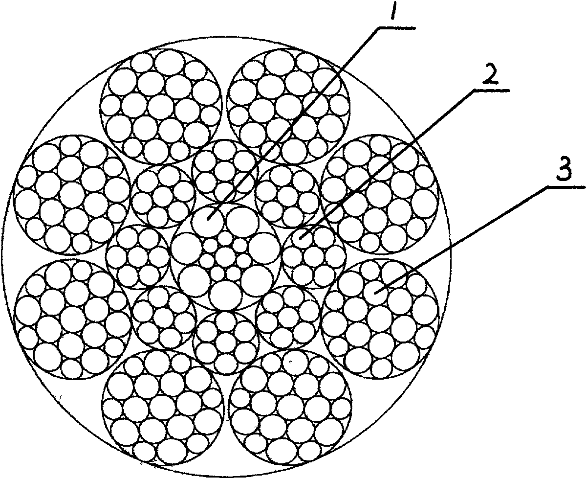
[0018] Embodiment: Stainless steel wire rope with CFRC8×19W structure, diameter 5.5mm, tensile strength 2160MPa, tempering in a continuous tempering furnace with hydrogen as protective gas, tempering temperature is 600~700°C; tempering time is 150~ 260 seconds, stainless steel wire rope for double-rope pull test (steel rope bypasses φ29mm pulley, pulley-to-rope ratio is 5.27:1), the breaking force of the whole rope is greater than 45KN, the breaking force of a single rope is greater than 26kN, and the steel wire rope is tempered. The bearing capacity is greatly improved, and its bearing capacity is 30-35% higher than that of ordinary aerospace steel wire ropes of the same specification.


PUM

PropertyMeasurementUnit
tensile loadaaaaaaaaaa

Abstract

The invention relates to a novel stainless steel wire for spaceflight. The structure of the novel stainless steel wire is CFRC8*19W or CFRC8*17S and is formed by twisting a central strand, eight inner-layer strands and eight outer-layer strands in one step, wherein the structure of the central strand is 1+7+7 and is formed by twisting fifteen steel wires in one step, the structure of eight inner-layer strands is 1+6 and is formed by twisting seven steel wires in one step, and the structure of the eight outer-layer strands is 1+6+6 / 6 or 1+8+8 and is formed by twisting nineteen or seventeen steel wires in one step. The novel stainless steel wire for spaceflight can greatly enhance the bearing capability by being tempered in a continuous tempering furnace with protection and has the advantages of high bending and fatigue resistant property, good flexible property and abrasion resisting property, long service life, good safety property, and the like.

Description

technical field [0001] The invention relates to a stainless steel wire rope for aerospace, belonging to the technical field of metal products. Background technique [0002] The existing stainless steel wire ropes for aerospace are mainly 6×7+IWS, 6×19+IWS and other structures. The strands of the steel wire rope are twisted by layers of steel wires of the same diameter, and the steel wires of adjacent layers are in point contact. , and the steel wire rope is not tempered after the twisting is completed. When the steel wire rope is bent around the drum or pulley, the steel wire in the strand is subjected to additional bending, resulting in secondary bending stress. The wear resistance is poor, the service life of the wire rope is low, and there are potential safety hazards. At present, there is no CFRC8×19W or CFRC8×17S aerospace stainless steel wire rope on the market. The same technology has not been reported in the public media. Contents of the invention [0003] The p...

Claims


Application Information

Patent Timeline
Patent Type & Authority Applications(China)
IPC IPC(8): D07B1/10C21D9/52
Inventor 张家琦林德均
Owner GUIZHOU WIRE ROPE
Why Eureka
Try Eureka