
Downlink movable mould frame and walking method thereof

A mobile formwork and traverse technology, which is applied in the erection/assembly of bridges, bridges, buildings, etc., can solve the problems of high quality dispersion of finished beams, inability of outriggers to realize self-propelled, and large workload, and reduce the number of traverse equipment. , the effect of light weight and strong bearing capacity

Active Publication Date: 2011-08-17
CHINA RAILWAY MAJOR BRIDGE ENG GRP CO LTD
View PDF0 Cites 2 Cited by
  • Summary
  • Abstract
  • Description
  • Claims
  • Application Information

AI Technical Summary

Problems solved by technology

The shortcomings of the conventional self-propelled method of the mobile formwork are: the lateral movement of the bottom formwork system requires more lateral movement equipment, high cost, and many processes; the legs of the mobile formwork cannot be self-propelled, and other lifting equipment must be cooperated Increased costs, when the site terrain conditions are poor and the lifting equipment is difficult to use, the transfer of the outriggers becomes the bottleneck of the construction of the mobile formwork; the formwork of the mobile formwork needs to be adjusted piece by piece in each construction cycle, and the workload is heavy , high quality dispersion of finished beams

Method used


Image

  • Downlink movable mould frame and walking method thereof
  • Downlink movable mould frame and walking method thereof
  • Downlink movable mould frame and walking method thereof

Examples


Embodiment Construction

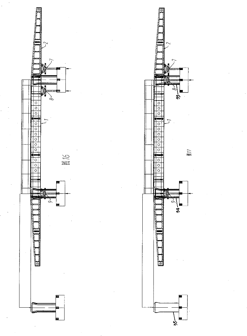
[0047] Such as figure 1 As shown, the concrete box girder 32 that has been poured between the rear pier body 35 and the middle pier body 34, the two main beams 1 below the concrete box girder and on both sides of the pier body, and the guide beams 2 ( is the front guide beam and the rear guide beam), the internal mold system 3 ( figure 2 Middle), the wing plate formwork system 4, the side formwork system 5, and the bottom formwork system 6 installed on the main beam 1, the two front outriggers 7 arranged under the guide beam 2, and the two front outriggers 7 arranged under the front end of the main beam 1 The middle outrigger 8, the two rear outriggers 9 arranged under the rear end of the main beam 1, and the longitudinal and lateral movement system 10 arranged between the main beam 1 and each outrigger.

[0048] Such as figure 2 As shown, the structure on the middle outrigger is used for illustration, and the structure of the front outrigger and the rear outrigger is the ...


PUM


Abstract

The invention discloses a downlink movable mould frame and a walking method thereof. The downlink movable mould frame comprises a girder, a guide beam connected at two ends of the girder and a mould frame system arranged on the girder. The downlink movable mould frame is characterized in that: three groups of legs are arranged below the girder; the leg comprises a middle leg and a rear leg arranged at the front end and rear end of the girder; the front guide beam is closed to the front leg arranged below the girder; a longitudinal and transverse beam system of the leg, the girder and the guidebeam and a lifter of the girder and the guide beam are arranged between the middle leg the rear leg, the front leg and the girder and the guide beam. The invention realizes walking automation of themovable mould frame and needs no extra cranes so as to strengthen the adaptability of the movable mound frame and enhance the economic competitiveness; the girder carries the external template to movetransversely so that the transverse devices of the templates are reduced, and the amount of the transverse oil cylinders of the total set of movable mould frames is reduced by above 60percent; the invention realizes demoulding and mould closing integrally without regulating templates one by one, thereby reducing the labour amount, simplifying the procedure and greatly improving the degree of mechanization.

Description

technical field [0001] The invention belongs to bridge construction technology, and in particular relates to a mobile box girder construction formwork and a running method of the mobile box girder construction formwork during the construction of a bridge engineering superstructure box girder. Background technique [0002] The mobile formwork can be divided into two types according to the location of its running mechanism. The traveling mechanism is located above the concrete box girder, which is called the upward moving formwork, and the running mechanism is located below the concrete box girder, which is called the downward moving formwork. Mobile formwork is a kind of box girder cast-in-place equipment that can be self-propelled, and its self-propelled method and efficiency have always attracted people's attention. The walking of the mobile formwork includes the vertical movement, lateral movement and lifting of the formwork. The longitudinal movement is to move the mobil...

Claims


Application Information

Patent Timeline
Patent Type & Authority Patents(China)
IPC IPC(8): E01D21/00
Inventor 秦顺全马涛姚森朱斌章勋桁
Owner CHINA RAILWAY MAJOR BRIDGE ENG GRP CO LTD
Learn More