
Single redundant bit digital correction method used for assembly line A/D converter

A digital correction and converter technology, applied in the direction of analog/digital conversion, analog-to-digital converter, code conversion, etc., can solve the problems of layout area, power consumption input and output delay time increase, etc., to reduce the total number of stages, reduce The effect of the series

Active Publication Date: 2009-11-18
CHONGQING GIGACHIP TECH CO LTD
View PDF0 Cites 16 Cited by
  • Summary
  • Abstract
  • Description
  • Claims
  • Application Information

AI Technical Summary

Problems solved by technology

[0006] In order to overcome the increase in layout area, power consumption and input-output delay time caused by too many pipeline stages required when the conventional digital correction method for pipeline A / D converter is applied to high-speed and high-precision A / D converter, And the problem of negative overflow and positive overflow of the input signal cannot be identified. The present invention provides a single redundant bit digital correction method for the pipeline A / D converter. The technical solution adopted includes the following steps:

Method used


Image

  • Single redundant bit digital correction method used for assembly line A/D converter
  • Single redundant bit digital correction method used for assembly line A/D converter
  • Single redundant bit digital correction method used for assembly line A/D converter

Examples


Embodiment Construction

[0037] The specific implementation manners of the present invention are not limited to the following description, and are now further described in conjunction with the accompanying drawings.

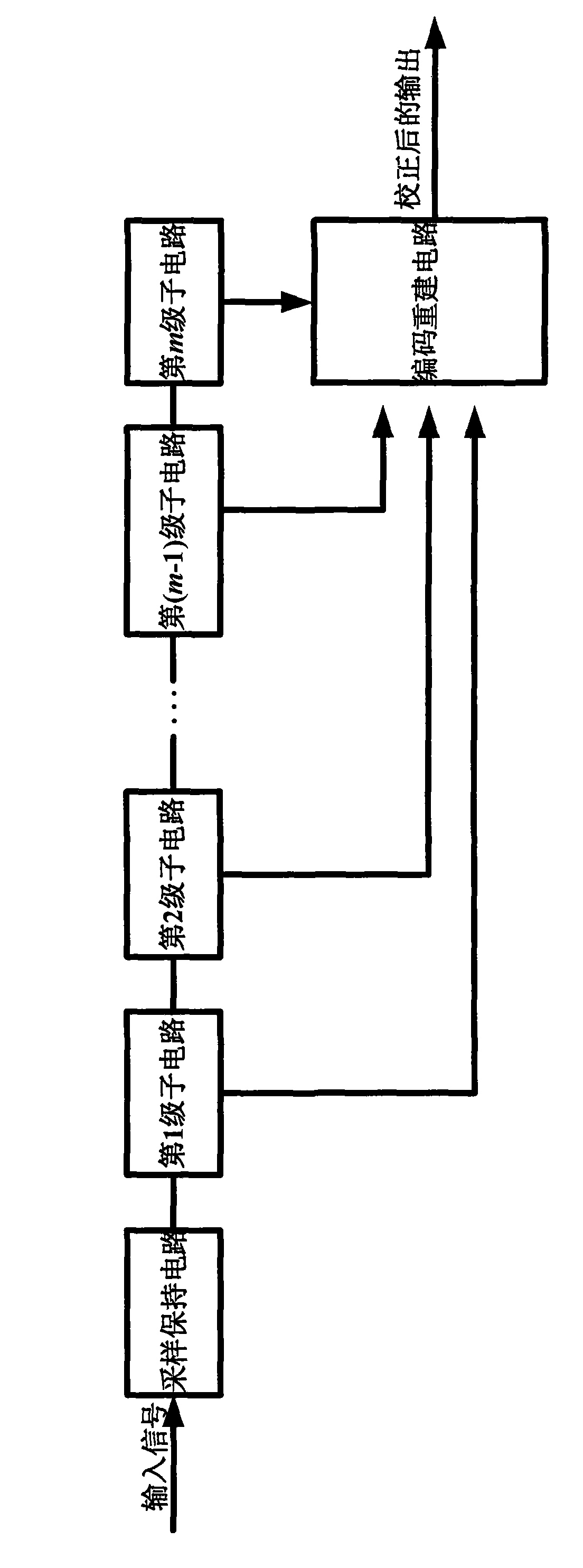
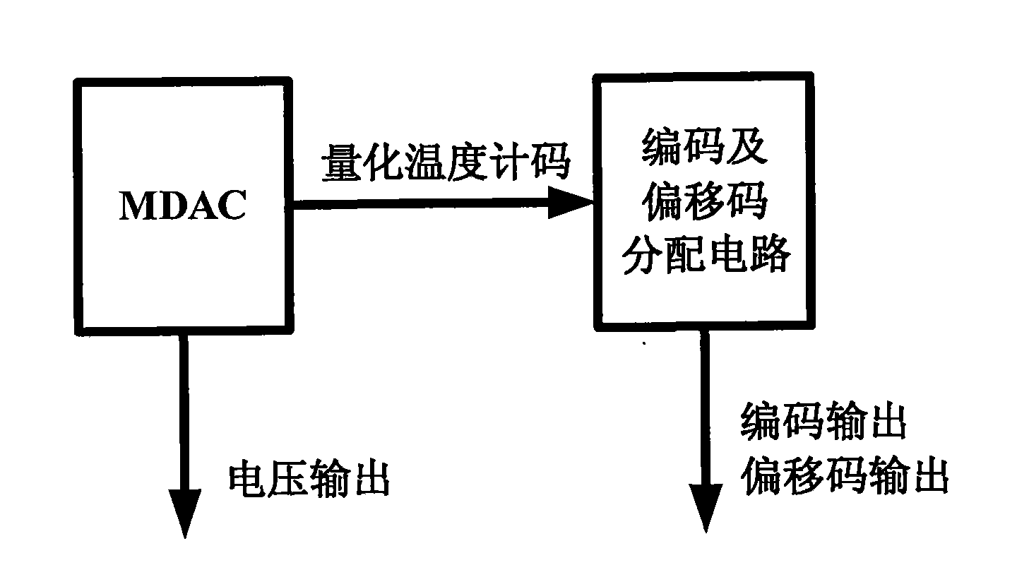
[0038] The overall structure schematic diagram of pipeline A / D converter in the inventive method is as figure 2 shown. The structure of the entire pipeline A / D converter includes a sample-and-hold circuit, m sub-circuits and a code reconstruction circuit. Its working principle is: the external input signal is sent to the first-level sub-circuit through the sample-and-hold circuit, and the first-level The sub-circuit quantifies its input voltage to obtain the quantized thermometer code, and calculates the analog voltage corresponding to the quantized thermometer code, that is, obtains the quantized voltage, then subtracts the quantized voltage from the input voltage to obtain the residual voltage, and amplifies the residual voltage and shift to the middle of the reference voltage interv...


PUM


Abstract

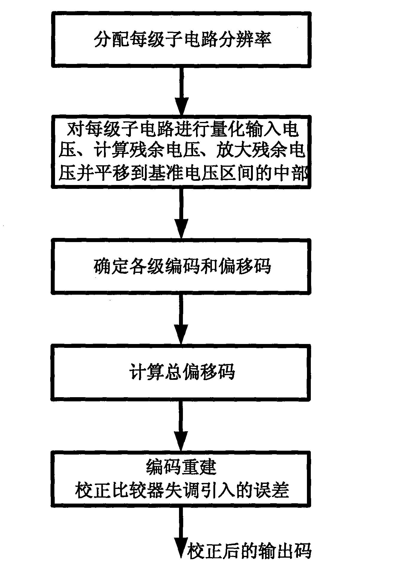
The invention discloses a single redundant bit digital correction method used for an assembly line A / D converter, which comprises the steps of: 1) distributing the resolution of each stage of sub circuit; 2) quantizing each stage of sub circuit and inputting voltage to each stage of sub circuit, calculating residual voltage, amplifying the residual voltage and translating the residual voltage to the middle part of a reference voltage interval; 3) determining codes and offset codes of each stage; 4) calculating the total offset codes; and 5) reconstructing the codes and correcting the error caused by comparator imbalance so as to obtain the output codes after correction. Compared with the existing conventional assembly line A / D converter digital correction method, the method has the following advantages of: flexibly distributing the resolution of each stage of sub circuit and obviously reducing assembly line stage number of a high speed and high precision A / D converter, thereby greatly saving the territory area, power consumption and shortening input-output delay. The method firstly provides a coding method of a plurality of positive redundant codes and a plurality of negative redundant codes, after the assembly line A / D converter is corrected by the method, an overflow bit thereof can mark the negative overflow and positive overflow of input signals, namely, bidirectional overflow. The method is applicable to the assembly line A / D converter, in particular to the field of digital correction of the high speed and high precision A / D converter.

Description

technical field [0001] The invention relates to a single redundant bit digital correction method, in particular to a single redundant bit digital correction method used for pipeline A / D converters. Its direct application field is the digital correction field of pipeline A / D converter. Background technique [0002] The circuit structure of A / D converter mainly includes successive comparison structure, integral structure, full parallel (flash) structure, hierarchical structure, pipeline structure and delta-sigma oversampling structure, etc. The main circuit structure involved in the high-speed and high-precision A / D converter circuit is a pipeline structure. [0003] The basic idea of ​​the pipeline structure was proposed by S.H.Lewis et al. in 1987. Its principle is to use the low-precision A / D converter to connect in a pipeline to realize the high-precision A / D converter. In 1990, B.Ginetti and others introduced the basic idea of ​​redundant bits on this basis, that is, th...

Claims


Application Information

Patent Timeline
Patent Type & Authority Applications(China)
IPC IPC(8): H03M1/14
CPCH03M1/0695H03M1/168
Inventor 李婷王育新沈晓峰周述涛刘涛徐鸣远李儒章何开全
Owner CHONGQING GIGACHIP TECH CO LTD
Learn More