Automatic calibration method for CT projection center

An automatic correction and projection center technology, applied in photography, optics, instruments, etc., can solve the problems of increasing the number of scans and measurement time, consuming the life of ray sources and detectors, and cumbersome problems, so as to save measurement time and prolong the effective working life Effect

Inactive Publication Date: 2009-11-25
INST OF PROCESS ENG CHINESE ACAD OF SCI
View PDF0 Cites 16 Cited by
  • Summary
  • Abstract
  • Description
  • Claims
  • Application Information

AI Technical Summary

Problems solved by technology

For the measurement of CT applied to large fixed equipment, such as multiphase flow reactors, the implementation of the special model method needs to remove the measured pipe section from the CT field of view (FOV) in order to perform special phantom correction, which is relatively cumbersome
Another disadvantage of using model correction is to increase the number of scans and measurement time, which consumes the life of the radiation source and detector
Moreover, under some working conditions of industrial CT, the detector or ray source will move slightly due to temperature or other reasons, and it is difficult for the naked eye to distinguish such anomalies from the reconstructed image. Therefore, the artifacts formed cannot be automatically completed by the model correction method. Correction of projection center, resulting in distorted measurement results

Method used


Image

  • Automatic calibration method for CT projection center
  • Automatic calibration method for CT projection center
  • Automatic calibration method for CT projection center

Examples


Embodiment Construction

[0034] The present invention can be used in various CT non-destructive testing fields. The technical details of the present invention will be described below by taking the detection of cross-sectional material distribution in a circulating fluidized bed reactor as an example.

[0035] Circulating fluidized bed reactors are widely used in petroleum smelting, boilers, metallurgy and other fields. The cross-sectional material distribution in the reactor is an important indicator of the operating status of the reactor. CT can measure the cross-sectional view of the reactor material distribution without interference , has aroused great interest in the industry in recent years. This implementation example is to apply CT to the inlet section of the riser of the circulating fluidized bed for measurement.

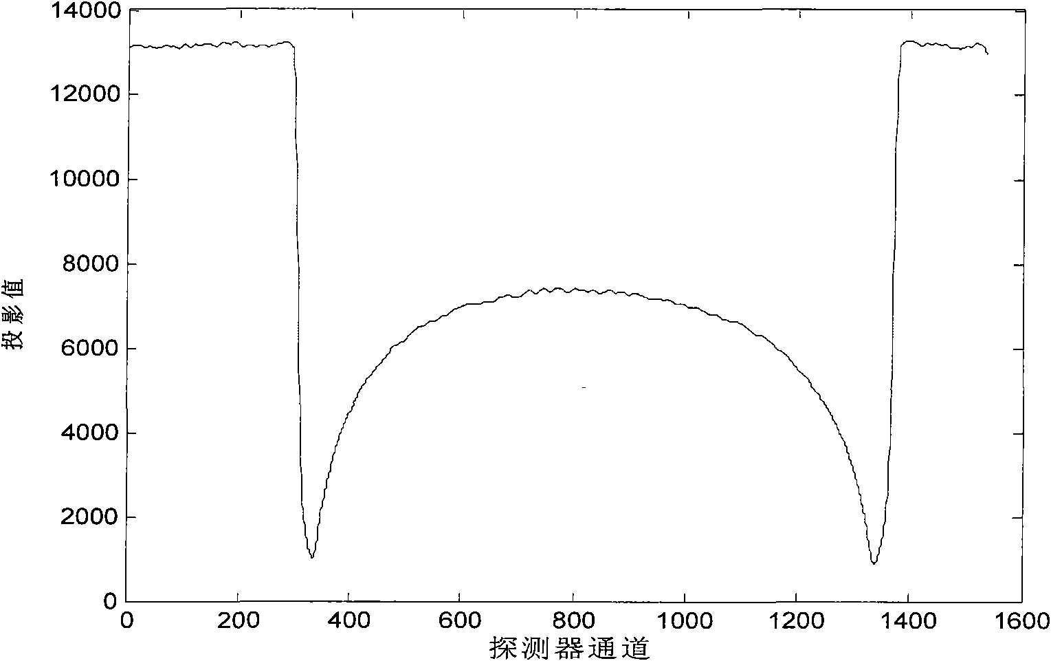
[0036] The CT machine used in this implementation example belongs to the third-generation X-ray CT, and the detectors are arranged in an equidistant linear array, with a total of 15...


PUM


Abstract

The invention provides an automatic calibration method for a CT projection center, which comprises the following steps of: 1) using CT to perform all-round scanning on a measured object to obtain original projection data of the measured object in various detector units of a detector array under different angles; 2) performing data processing on the original projection data to find the positions of projection points of the edges of the measured object in the detector array; and 3) calculating the CT projection center according to the positions of the projection points of the edges of the measured object in the detector array, and calibrating the original projection data to obtain final two-dimensional tomography data. The method can calibrate the central projection position of the CT without adopting a special die body and moving the measured objects; and various calibration steps of the method can be established into a reconstruction pre-processing program to automatically run so as to save measurement time, and prolong the effective service life of diographic sources and detectors.

Description

technical field [0001] The invention belongs to the technical field of non-destructive testing, in particular, the invention relates to a method for correcting the CT projection center. Background technique [0002] Computed tomography (CT) is widely used in medical imaging, industrial non-destructive testing and other fields. Its basic principle is that the radiation source emits high-energy radiation. After passing through the object to be measured, the detector detects the attenuated radiation signal. The projection information of the ray under the angle to the measured object is applied to the corresponding reconstruction algorithm to calculate the two-dimensional information of the measured section. CT can be divided into five generations according to the data acquisition methods of the ray source-detector movement. At present, the more commonly used ones are the first-generation scanning mode of translation-rotation and the third-generation scanning mode of rotation-ro...

Claims


Application Information

Patent Timeline
Patent Type & Authority Applications(China)
IPC IPC(8): A61B6/03G01N23/04G03B42/02
Inventor 孟凡勇王维李静海
Owner INST OF PROCESS ENG CHINESE ACAD OF SCI
Why Eureka
Try Eureka