Optical fibre sensor structure

An optical fiber sensor and optical fiber technology, applied in the field of optical measurement, can solve the problems of low sensitivity, complex sensor measurement system and high cost

Active Publication Date: 2009-11-25
SHANGHAI BRANCH FUZHOU GAOYI COMM CO LTD
View PDF0 Cites 20 Cited by
  • Summary
  • Abstract
  • Description
  • Claims
  • Application Information

AI Technical Summary

Problems solved by technology

Among them, the sensing and measuring system of the spectral absorption sensor is more complex, with more optical components, higher cost, and poor stability; the dye indicator sensor is easily limited by the chemical reaction speed, sensitive to ambient temperature and humidity, and has poor reversibility; Variable sensors are easily affected by other gases and need to be adjusted frequently, and their reliability and stability are poor; fluorescent sensors often generate weak signals due to weak pump light, so the detection system is complicated and the system cost is high; The evanescent wave sensor has the advantages of simple structure design and low cost, but it also has the disadvantage of low sensitivity

Method used


Image

  • Optical fibre sensor structure
  • Optical fibre sensor structure
  • Optical fibre sensor structure

Examples


Embodiment Construction

[0022] The present invention will be further described in conjunction with the accompanying drawings and specific embodiments.

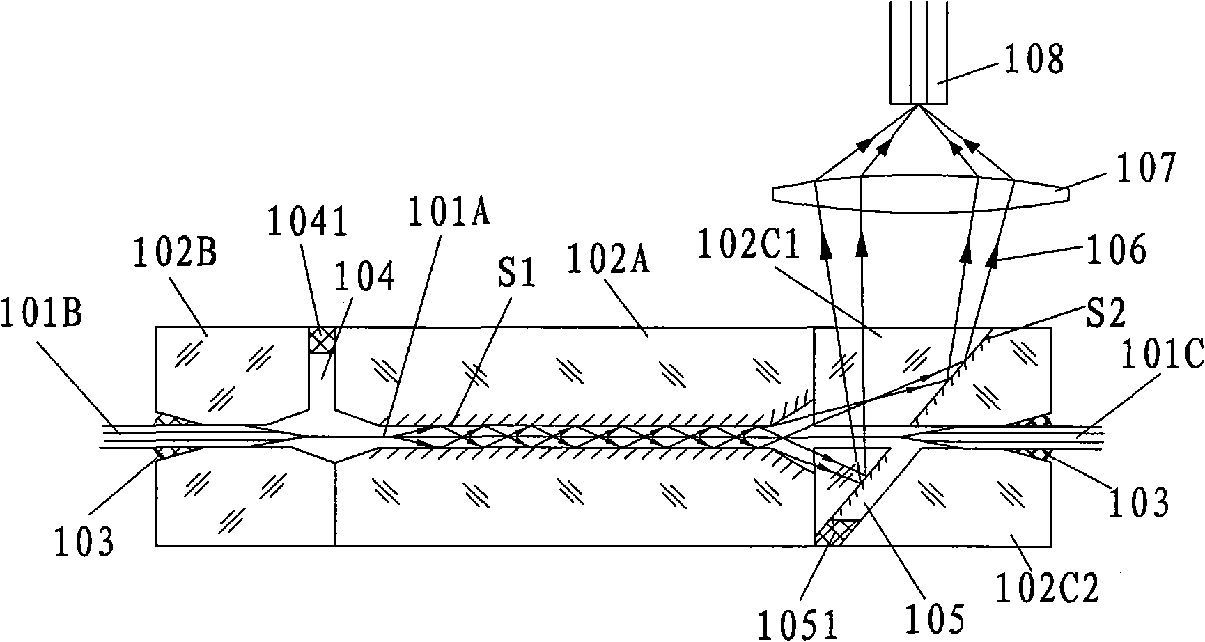
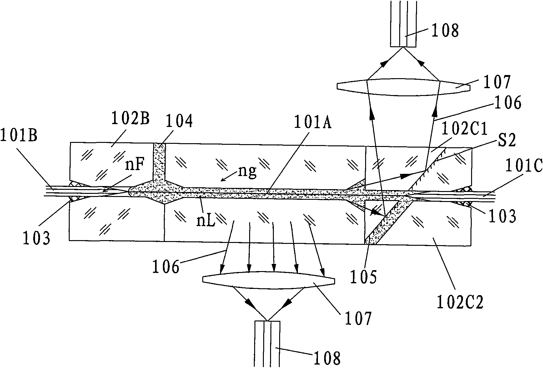
[0023] In the optical fiber sensor structure of the present invention, the laser is input through the optical fiber, and the evanescent wave generated by the laser in the optical fiber excites the surrounding gas or liquid substance, and the obtained fluorescence or Raman light is collected, and then passed through The spectrometer performs spectrum analysis and processing to obtain detection results.

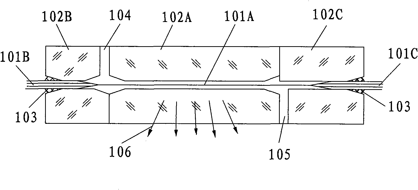
[0024] refer to figure 1 In the shown embodiment one, 101A is a conventional section of an optical fiber, 101B and 101C are tapered sections of an optical fiber, 102A, 102B, and 102C are three-section fiber capillary sleeves, and 104 and 105 are respectively an inlet channel and an outlet channel, 103 is the glue for bonding the tapered sections 101B, 101C of the filling fiber and the fiber capillary sleeves 102B, 102C, and 106 is the fluorescence or...


PUM


Abstract

The invention relates to optical measurement field, particularly relates to optical fibre sensor structure, laser is inputted through optical fibre, evanescent wave generated in the optical fibre by laser excites peripheral gas or liquid materials to obtain fluorescence or Raman light, collecting the fluorescence or Raman light and proceeding frequency analysis and processing through a spectrometer to obtain a testing result. The optical fibre is disposed in capillary sleeve which is glued by three section of capillary sleeves, specifically includes a first capillary sleeve which is regular section of optical fibre in tube; a second capillary sleeve which is cone section of optical fibre in tube; a third capillary sleeve which is cone section of optical fibre in tube. The invention has technical advantages of removing effect of pump light to measuring light, implementing a optical fibre gas sensor or optical fibre liquid sensor with simple structure and test sensitivity.

Description

technical field [0001] The invention relates to the field of optical measurement, in particular to using the evanescent wave generated by the input laser in the optical fiber to excite a gas or liquid substance in a capillary structure to obtain a fluorescence spectrum or a Raman spectrum, and then use a spectrometer for spectrum analysis, thereby realizing Optical fiber sensor structure for detecting test gas or liquid substances. Background technique [0002] Optical fiber gas sensor or optical fiber liquid sensor has been widely used due to its advantages of good electrical insulation, strong anti-electromagnetic interference ability, explosion-proof, long-distance long-term online measurement, simple structure of sensing unit, stability and reliability, and easy composition of optical fiber sensor network. It is used in the detection of various toxic and harmful gases or liquid substances, the monitoring of air pollution and industrial waste gas, industrial wastewater, a...

Claims


Application Information

Patent Timeline
Patent Type & Authority Applications(China)
IPC IPC(8): G01N21/64G01N21/65G02B6/26
Inventor 吴砺陈燕平孙朝阳凌吉武
Owner SHANGHAI BRANCH FUZHOU GAOYI COMM CO LTD
Why Eureka
Try Eureka