Five degree-of-freedom manipulator

A technology of robotic arms and degrees of freedom, applied in the field of robotic arms, can solve the problems of low mass and high stiffness, and achieve the effects of low mass, high stiffness, and easy assembly and maintenance.

Inactive Publication Date: 2009-12-02
HARBIN INST OF TECH
View PDF0 Cites 36 Cited by
  • Summary
  • Abstract
  • Description
  • Claims
  • Application Information

AI Technical Summary

Problems solved by technology

[0003] The purpose of the present invention is to provide a five-degree-of-freedom mechanical arm to solve the problem that there is no mechanical arm with accurate positioning, high precision, small mass and high rigidity for use with intelligent wheelchairs

Method used


Image

  • Five degree-of-freedom manipulator
  • Five degree-of-freedom manipulator
  • Five degree-of-freedom manipulator

Examples


specific Embodiment approach 1

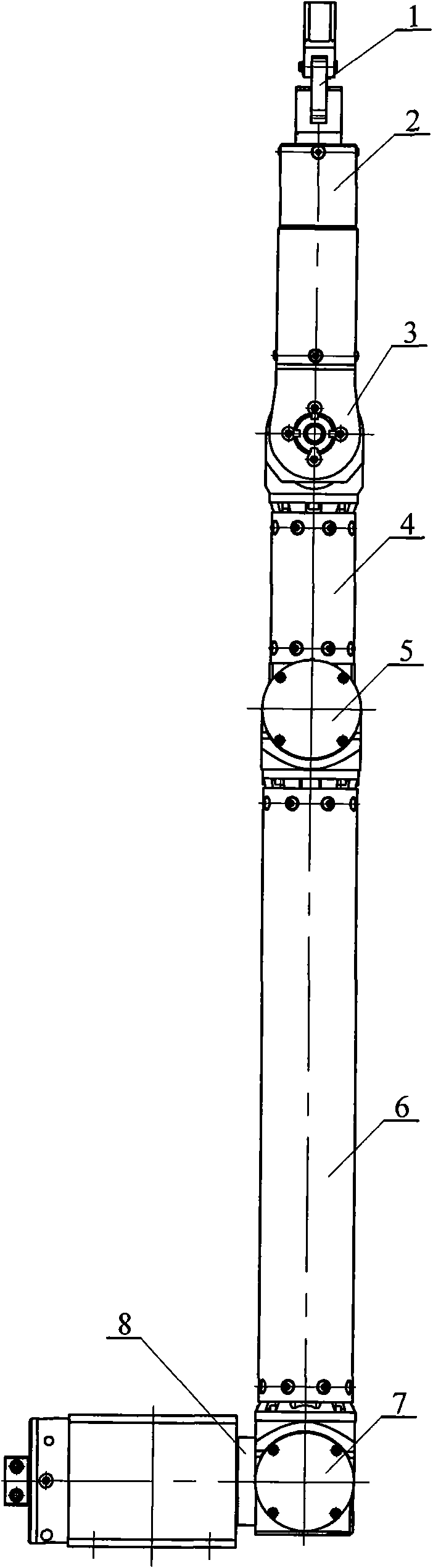
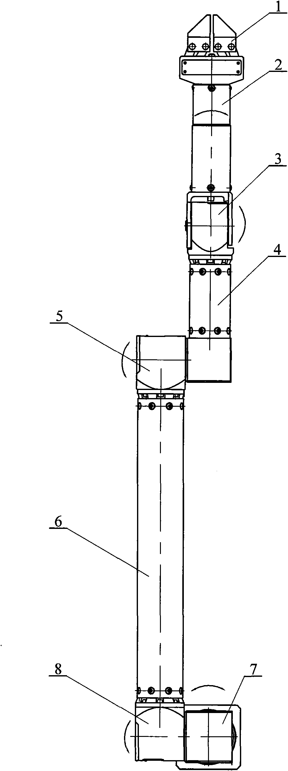
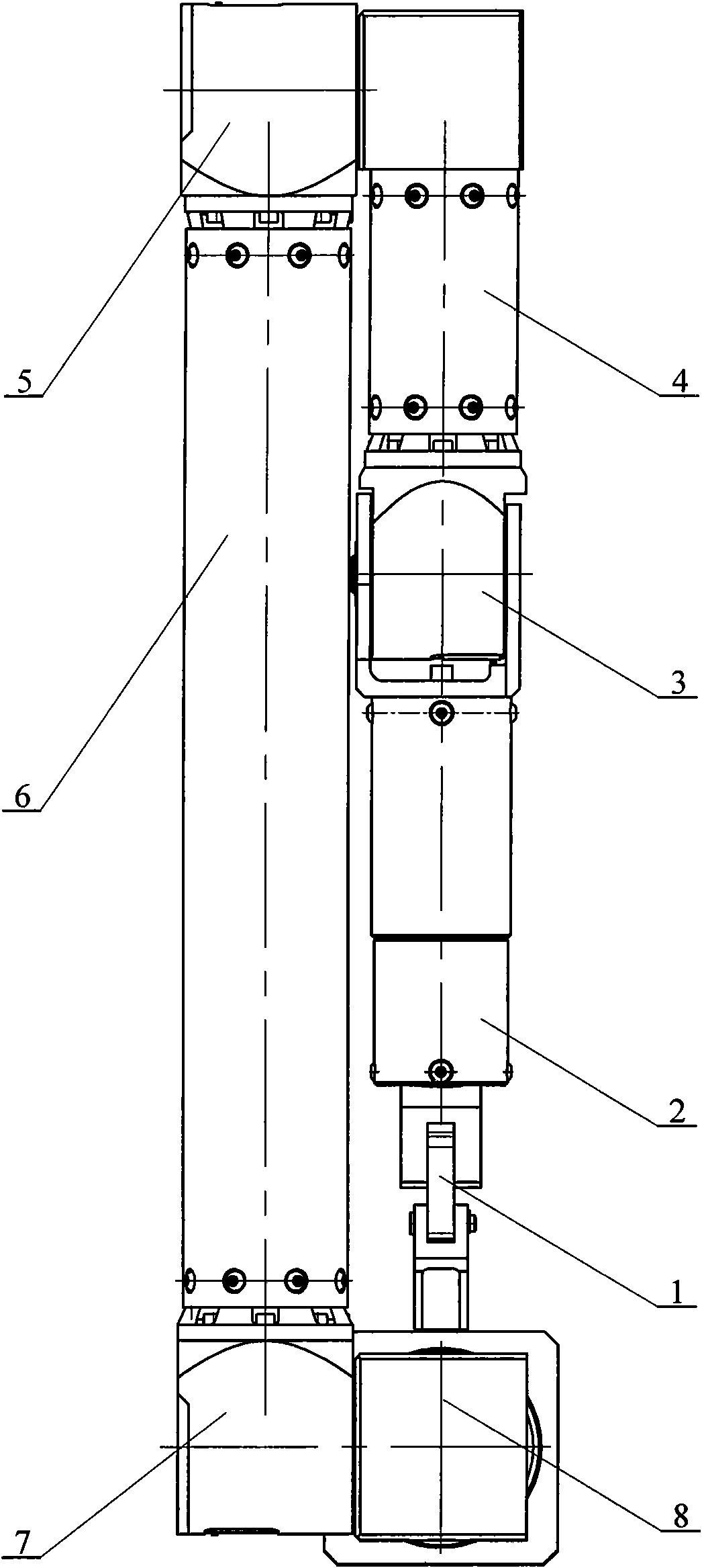
[0007] Specific implementation mode one: combine Figure 1 to Figure 9 Describe this embodiment, the mechanical arm described in this embodiment is constituted by a mechanical arm and a claw 1; Composed with the shoulder rotary joint 8; the disc drive servo motor 102 of the hand claw 1 is fixed in the spindle 201 of the wrist rotary joint 2 (fixed by screws), the claws are replaceable, and various claws can be replaced To facilitate clamping objects of different shapes, the wrist swivel joint connecting part 204 of the wrist swivel joint 2 is fixedly connected to the upper end of the auxiliary connecting plate 301 of the wrist joint 3, and the connecting end of the second connecting part 311 of the wrist joint 3 is connected to the small The upper end of the arm 4 is fixedly connected, the rear lower end of the small arm 4 is fixedly connected with the large gear of the elbow joint 5, the elbow joint bearing seat 512 in the elbow joint 5 is fixedly connected with the upper end...

specific Embodiment approach 2

[0008] Specific implementation mode two: combination figure 1 with Figure 5 To illustrate this embodiment, the wrist swivel joint 2 in this embodiment is composed of a mandrel 201, a wrist swivel joint servo motor 202, a wrist swivel joint housing 203, a wrist swivel joint connector 204 and two wrist swivel joint bearings 205; The lower end of the mandrel 201 is installed in the wrist revolving joint housing 203, and two wrist revolving joint bearings 205 are installed between the mandrel 201 and the wrist revolving joint housing 203, and the wrist revolving joint servo motor 202 is installed in the inner cavity of the mandrel 201 Among them, the output shaft of the wrist swivel joint servo motor 202 passes through the center hole of the lower end surface of the mandrel 201 and is fixedly connected to the central boss on the upper end of the wrist swivel joint connector 204, and the lower end of the wrist swivel joint housing 203 is connected to the wrist swivel joint The u...

specific Embodiment approach 3

[0009] Specific implementation mode three: combination figure 1 with Figure 4 Illustrate this embodiment, the claw 1 described in this embodiment is composed of, a disc drive servo motor 102, a rotating screw 103, a palm 104, a gear sleeve 105, two fingers 106, two parallel rods 107, two hands The claw seat 108 and two claws 109 are composed; the output shaft of the disc drive servo motor 102 is affixed to the input end of the rotating screw 103, and the output end of the rotating screw 103 passes through the center hole of the palm 104 and is arranged on the In the center of the palm of the palm 104, the gear sleeve 105 that is threadedly connected with it is housed on the screw lever of rotating leading screw 103, and the left side and the right side of rotating leading screw 103 are respectively provided with a finger 106 and a parallel rod 107, and described finger 106 A plurality of teeth are processed on the circular arc end surface of the lower end, and the gear slee...


PUM


Abstract

The invention discloses a five degree-of-freedom manipulator, and relates to a manipulator. The manipulator aims to solve the problem that no manipulator which is matched with intelligent wheelchairs and has the advantages of accurate positioning, high precision, small mass and large rigidity exists at present. A disc type driving servomotor of a paw is fixed in a mandrel of a wrist revolute joint, a wrist revolute joint connecting piece of the wrist revolute joint is fixedly connected with the upper end of an auxiliary connecting plate of a wrist joint, a connecting end of a second connecting piece of the wrist joint is fixedly connected with the upper end of a small arm, the lower-rear end of the small arm is fixedly connected with a large gear of an elbow joint, an elbow joint bearing support in the elbow joint is fixedly connected with the upper end of a big arm, the lower end of the big arm is fixedly connected with a sixth connecting piece of a shoulder joint, and the sixth connecting piece of the shoulder joint is fixedly connected with a shoulder revolute joint mandrel of a shoulder revolute joint. The manipulator can replace human arms to finish operation tasks on certain specific occasions. The manipulator has the advantages of simple structure, accurate positioning, high precision, small mass, large rigidity, full functions, safe and reliable use, simple and convenient assembly and maintenance, and lower cost.

Description

technical field [0001] The invention relates to a mechanical arm, in particular to a mechanical arm installed on a wheelchair for disabled persons. Background technique [0002] With the advent of the era of great material abundance and the improvement of human civilization, people, especially the disabled, increasingly need to use modern high-tech to improve their quality of life and freedom of life. Therefore, research on robotic wheelchairs for helping disabled people to walk has gradually become a hotspot. A smart wheelchair is a service robot that helps people with disabilities. Early smart wheelchairs only provided the basic function of wheelchairs, "walking". Since more and more disabled people are inconvenient to move, this gave birth to a plan to add a mechanical arm that can imitate human arm movements on the basis of the original smart wheelchair. Good for helping disabled people with simple tasks like picking locks and picking up small objects. Smart wheelchai...

Claims


Application Information

Patent Timeline
Patent Type & Authority Applications(China)
IPC IPC(8): A61G5/10B25J18/00B25J17/02B25J17/00B25J15/02B25J18/04
Inventor 李瑞峰关技来高云峰
Owner HARBIN INST OF TECH
Why Eureka
Try Eureka