
Fluidized-bed boiler

A fluidized bed boiler and fluidized bed technology are applied in the field of fluidized bed boilers, which can solve the problems of insufficient primary air volume, pollutant discharge, low desulfurization rate, etc., so as to improve fuel utilization rate, reduce pollutant discharge and desulfurization efficiency. high effect

Inactive Publication Date: 2009-12-02
NINGBO YINUO ENERGY TECH
View PDF0 Cites 30 Cited by
  • Summary
  • Abstract
  • Description
  • Claims
  • Application Information

AI Technical Summary

Problems solved by technology

[0003] At present, during the operation of domestic small and medium-sized fluidized bed boilers, the phenomenon of insufficient primary air volume and slag leakage of the air distribution plate often occurs due to wear and tear of components and reduced sealing performance of pipelines, which also causes large amount of return material and separation from the cyclone The secondary combustion of the unburned matter in the return pipe of the boiler; moreover, at present, a large number of domestic small and medium-sized fluidized bed boilers still have a low desulfurization rate, and these defects restrict the internal mass transfer and heat transfer of the existing fluidized bed boilers effect, as well as the function of the furnace charge returning to the furnace, thus affecting the boiler output and economic benefits, and causing excessive emissions of pollutants

Method used


Image

  • Fluidized-bed boiler

Examples


Embodiment Construction

[0016] The present invention will be further described in detail below in conjunction with the accompanying drawings and embodiments.

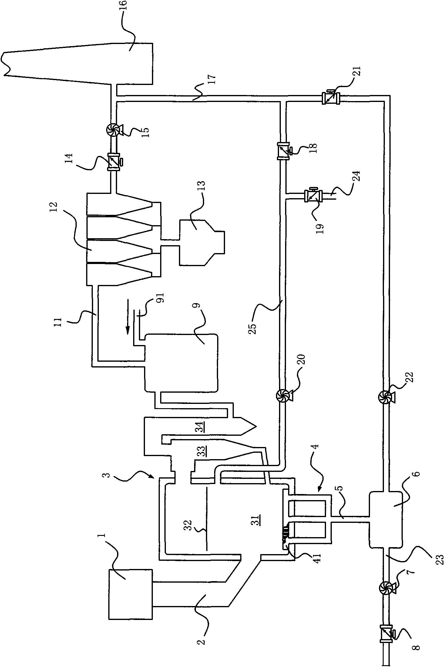
[0017] Such as figure 1 A fluidized bed boiler is shown, which includes a fuel tank 1 for storing coal or other fuels, and the fuel tank 1 is connected to a boiler body 3 .

[0018] The boiler body 3 comprises a circulating fluidized bed combustion chamber 31 connected to a cyclone separator 33; the fluidized bed height zone 32 is shown in the figure. The outlet of the cyclone separator 33 is connected with a heating assembly 34, and the heating assembly 34 includes a superheater, an economizer and an air preheater.

[0019] The bottom of the combustion chamber is provided with an air distribution plate 41 with a wind cap, which communicates with a blower 7 through the wind chamber 4, and the blower enters the combustion chamber 31 with compressed air through the wind chamber and the wind cap; the combustion process in the combustion chamber ...


PUM


Abstract

The invention provides a fluidized-bed boiler, which comprises a fluidized-bed combustion chamber. The bottom of the fluidized-bed combustion chamber is provided with a wind chamber of a wind distributor, and the fluidized-bed combustion chamber is communicated with a blower; combusted flue gas of the combustion chamber is exhausted from a chimney through an induced draught fan; the outlet of the induced draught fan is connected with a flue gas recirculation tube which is respectively communicated with the fluidized-bed combustion chamber and the wind chamber; an upper layer wind adjusting valve is arranged between the flue gas recirculation tube and the fluidized-bed combustion chamber; an upper layer fan is arranged between the upper layer wind adjusting valve and the combustion chamber; an air draft pipe with an air regulating valve is arranged between the upper layer fan and the upper layer wind adjusting valve; upper layer wind is formed by the air and flue gas; the blower is connected with an air-flue gas mixing chamber; the other end of the mixing chamber is communicated with the flue gas recirculation pipe through a flue gas secondary fan and a flue gas secondary regulating valve; and the upper part of the mixing chamber is communicated with the air chamber to form one-time wind. The fluidized-bed boiler has the advantages of improving the utilization rate of fuel, reducing the emission of pollutants, and having higher desulphurization efficiency and wide application of coal fuel.

Description

technical field [0001] The invention relates to the technical field of a boiler combustion device, in particular to a fluidized bed boiler with a flue gas recirculation device. Background technique [0002] The existing fluidized bed boiler structure includes a boiler body provided with a fluidized bed combustion chamber. The bottom of the combustion chamber is provided with an air distribution plate with a hood. The hood communicates with the primary air blower through the air chamber. The blower will Compressed air enters the combustion chamber through the air chamber and air cap, and the combustion flue gas in the boiler body passes through the heating component from the upper end of the cyclone separator, and then is led to the chimney by the induced draft fan through the dust collector to be discharged. One side of the fluidized bed combustion chamber communicates with a fuel tank. [0003] At present, during the operation of domestic small and medium-sized fluidized b...

Claims


Application Information

Patent Timeline
IPC IPC(8): F23C10/02F23C10/28F23J15/00
Inventor 徐国武沈舒舒朱世明肯内斯L·马龙陈金岳
Owner NINGBO YINUO ENERGY TECH
Learn More