Device and method for detecting leakage of seal chamber by infrared imaging technology

A technology for detecting and sealing a cavity is applied in the field of devices that use infrared imaging technology to detect the leakage of a sealed cavity, and can solve the problems of complex process, large influence of environmental temperature on detection results, and difficulty in detecting leakage.

Active Publication Date: 2009-12-02
BOYI TIANJIN PNEUMATIC TECH INST
View PDF0 Cites 16 Cited by
  • Summary
  • Abstract
  • Description
  • Claims
  • Application Information

AI Technical Summary

Problems solved by technology

[0002] There are many ways to detect the leakage of the sealed cavity. For example, filling the measured cavity with a certain pressure of gas (using air as the medium), and then observing the pressure drop through the pressure gauge to check whether there is leakage. The advantage is that the method is simple, but Due to the use of direct pressure to detect the pressure drop, the resolution is low, and it is difficult to detect when the leakage is small, and the detection results are greatly affected by the ambient temperature and the specific location of the leakage point cannot be determined
There is also a differential pressure leak detection method, that is, two identical measured cavities (one of which has no leakage) are connected to both ends of the differential pressure manometer, and then a certain pressure of gas is filled into the two measured cavities at the same time. , to observe the pressure difference change at both ends of the differential pressure manometer. It

Method used


Image

  • Device and method for detecting leakage of seal chamber by infrared imaging technology
  • Device and method for detecting leakage of seal chamber by infrared imaging technology
  • Device and method for detecting leakage of seal chamber by infrared imaging technology

Examples


Embodiment

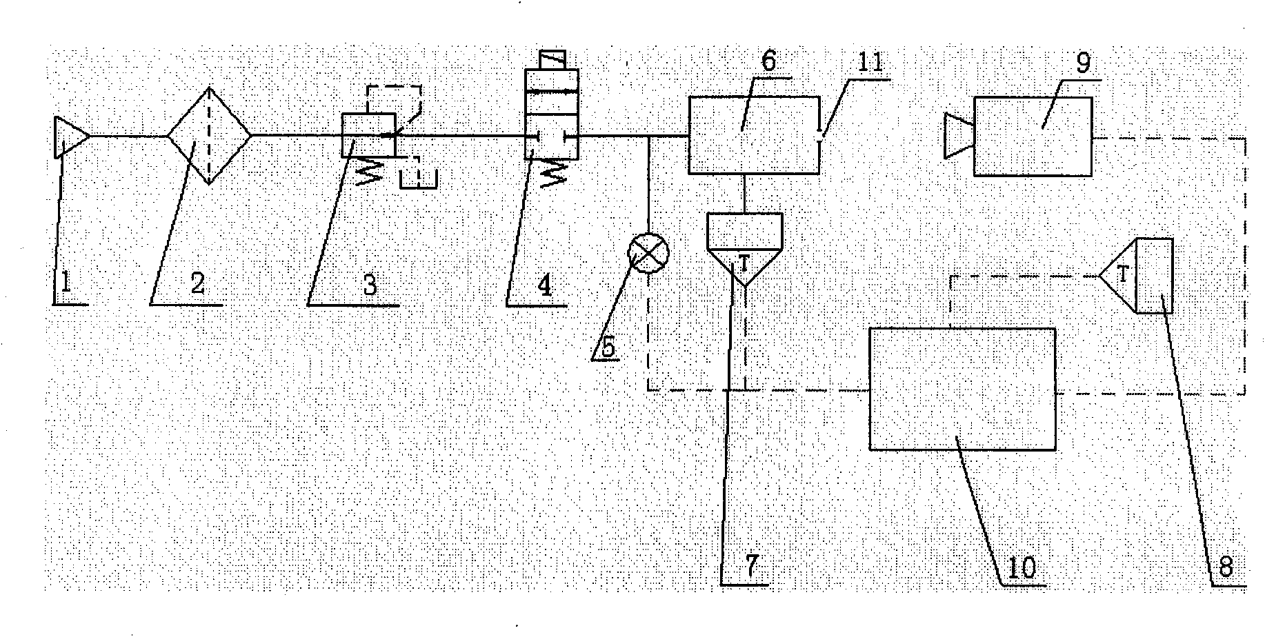
[0063] A device for detecting leakage of a sealed cavity using infrared imaging technology, comprising a gas source 1, a filter 2, a pressure regulating valve 3, a solenoid valve 4, a pressure sensor 5, a measured cavity 6, temperature sensors A 7, and a temperature sensor B8 , an infrared thermal imager 9 and a control system 10, the measured cavity 6 has a leak hole 11; the gas source 1, the filter 2, the pressure regulating valve 3, the solenoid valve 4 and the measured cavity 6 are connected in series through pipelines, and the pressure The sensor 5 is set on the pipeline between the solenoid valve 4 and the measured cavity 6, the measured cavity 6 and the control system 10 are respectively provided with a temperature sensor A7 and a temperature sensor B8, a pressure sensor 5, a temperature sensor A7, a temperature sensor B8 and the infrared camera 9 are respectively connected with the control system 10 through wires.

[0064] The method of using infrared imaging technolog...


PUM


Abstract

The invention provides a device for detecting leakage of a seal chamber by infrared imaging technology. The device comprises a gas source, a filter, a pressure regulating valve, an electromagnetic valve, a pressure sensor, a temperature sensor, a thermal infrared imager and a control system, wherein the pressure sensor, the temperature sensor and the thermal infrared imager are connected with the control system through lead wires respectively. A method for detecting the leakage of the seal chamber by the device comprises the following steps that a device to be detected reaches a thermodynamical equilibrium state after inflation, namely heat of a material around a vent released to airflow in unit time is equal to that of the material absorbed from atmosphere around the vent, and a leakage point can be determined through the position with reduced temperature detected by the thermal infrared imager; and the leakage amount can be determined through calculation of a computer in the control system. The device and the method have the advantages that the detecting device has simple structure, easy operation and low cost; the detecting method is practical, has small detection error, and can quickly and accurately detect the leakage point and the leakage amount of a chamber to be detected; and the detecting device and the method have strong applicability and wide application prospect.

Description

(1) Technical field [0001] The invention relates to a method for detecting gas leakage in a sealed cavity, in particular to a device and method for detecting the leakage of a sealed cavity using infrared imaging technology. (2) Background technology [0002] There are many ways to detect the leakage of the sealed cavity. For example, filling the measured cavity with a certain pressure of gas (using air as the medium), and then observing the pressure drop through the pressure gauge to check whether there is leakage. The advantage is that the method is simple, but Due to the use of direct pressure to detect the pressure drop, the resolution is low, and it is difficult to detect when the leakage is small, and the detection results are greatly affected by the ambient temperature and the specific location of the leakage point cannot be determined. There is also a differential pressure leak detection method, that is, two identical measured cavities (one of which has no leakage) ar...

Claims


Application Information

Patent Timeline
IPC IPC(8): G01M3/04
Inventor 陈乃克
Owner BOYI TIANJIN PNEUMATIC TECH INST
Why Eureka
Try Eureka