

Asymmetric double-core photonic crystal fiber based broadband mode converter
A technology of photonic crystal fiber and mode converter, applied in cladding fiber, optical waveguide and light guide, etc., can solve the problems of phase mismatch, high manufacturing process requirements, optical signal interference, etc., and achieve the effect of broadband mode conversion
Inactive Publication Date: 2011-01-05
JIANGSU UNIV
View PDF1 Cites 0 Cited by
- Summary
- Abstract
- Description
- Claims
- Application Information
AI Technical Summary
Problems solved by technology
Among them, the most common one is the mode converter based on fiber Bragg grating, but when fiber Bragg grating is used, the fundamental mode and the converted high-order mode are transmitted in the same optical fiber. Therefore, if the fiber Bragg grating cannot convert the fundamental mode to 100% If the high-order mode is used, there will be residual fundamental mode energy transmitted in the optical fiber, and these residual energy will interfere with the transmitted optical signal, thereby affecting the performance of the device
In addition, although this fiber grating mode has a high conversion efficiency greater than 99%, its operating bandwidth is very narrow, on the order of a few nanometers
The all-fiber mode converter based on photonic crystal fiber fusion technology can achieve high extinction ratio mode conversion in a wide bandwidth range, but this kind of device has high requirements in terms of manufacturing process, and it is difficult to achieve mass production.
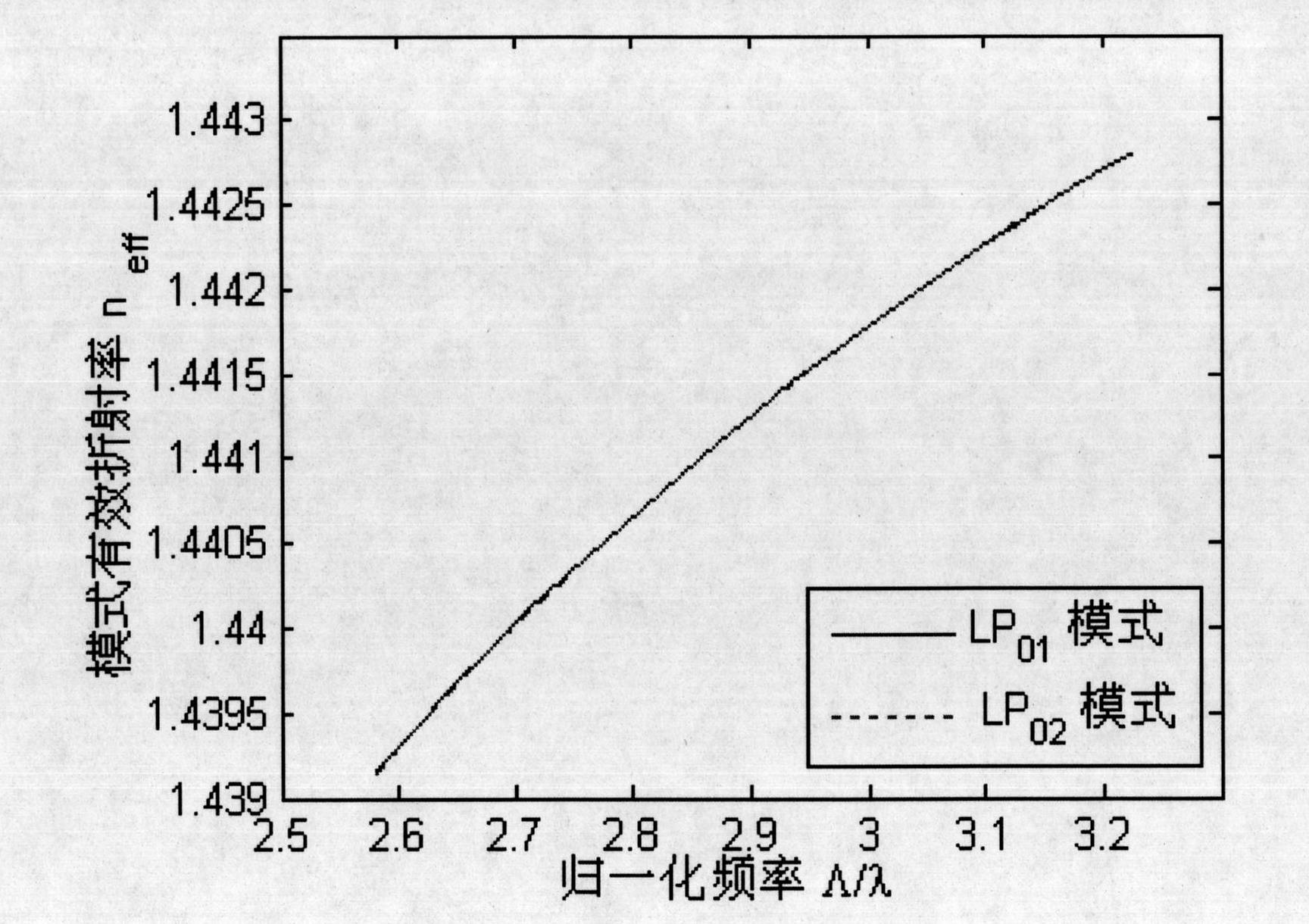
The application number is 200810021652.8, and the name is "a fiber mode converter" which discloses a mode converter based on an asymmetric dual-core photonic crystal fiber. This mode converter is made by making the fundamental mode (LP01) and The effective refractive index of the high-order mode (LP02) of the other core is equal to achieve efficient coupling between the fundamental mode and the high-order mode, that is, to use coupling to achieve mode conversion. The polarization-dependent loss of this mode converter is small and mass production can be realized. , but its defect is: the effective refractive index curves of the two modes in this structure can only intersect at one frequency point, and at other frequency points, because the effective refractive indices of the two modes are not equal, that is, the two phases do not match, According to the coupling theory, only partial coupling can be achieved, which directly leads to a decrease in conversion efficiency. Since the effective refractive index between the two modes can only be matched within a narrow frequency range, its operating bandwidth is narrow. , only 14nm
Method used
View moreImage
Smart ImageViewing Examples

Examples
Embodiment
Login to View More PUM
 Abstract
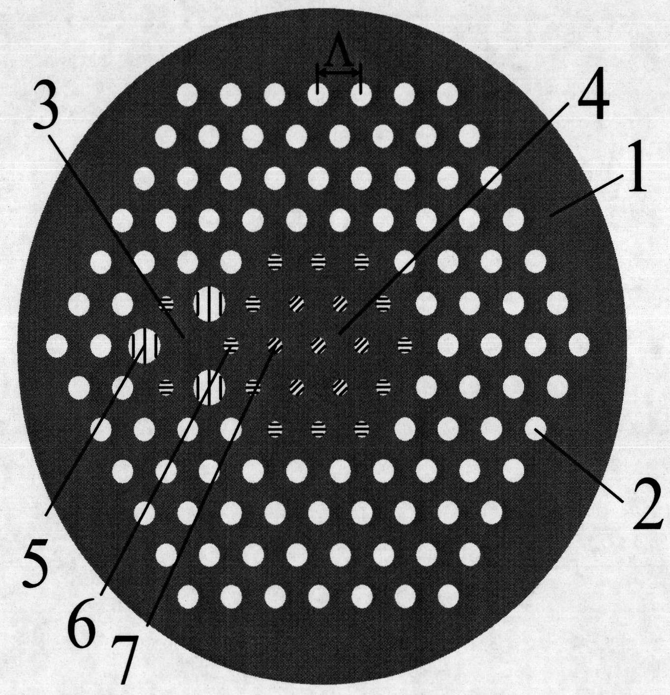
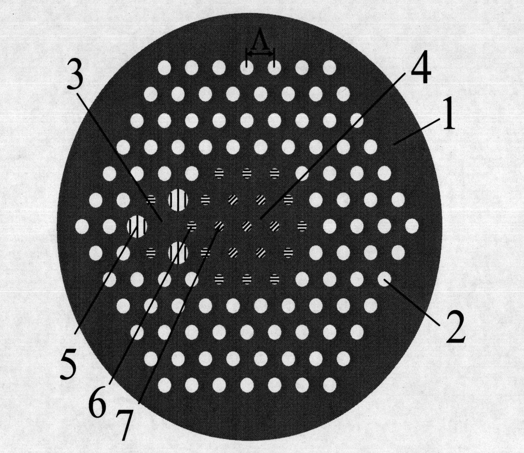
The invention discloses an asymmetric double-core photonic crystal fiber broadband mode converter, which consists of a matrix material and holes distributed on the matrix material. Each adjacent three holes form a regular triangular grid, the center of each hole is positioned on a node of the regular triangular grid respectively, a deficient air hole in the regular triangular grid forms a fiber core, and seven medium bars which are distributed on the nodes of the regular triangular grid form the fiber core, wherein the refractive indexes of the seven medium bars are lower than the refractive index of the matrix material; and air holes around the innermost layer of the fiber core comprise three large holes and three small holes, the diameters of the large holes are greater than the diameters of the small holes, the large holes and the small holes are arranged at intervals and distributed on the nodes of the regular triangular grid in turn, and the air holes of the inner layer close to the fiber core are the small holes. By changing the diameters of the air holes of two fiber core claddings and the refractive indexes of the medium bars doped in the fiber core, the effective refractive indexes of a base mode and a high-order mode are adjusted, the broadband mode conversion is realized, and the working bandwidth can reach 160 nanometers.
Description
A Broadband Mode Converter Based on Asymmetric Dual-Core Photonic Crystal Fiber technical field The invention relates to the technical fields of optical fiber communication and sensing, in particular to an optical fiber mode converter. Background technique A fiber mode converter is a device that converts between different mode fields in an optical fiber, and has important applications in the fields of optical communication networks and sensing. At present, a variety of new fiber structures are: one is the Bragg-type fiber using the photonic bandgap principle, and the mode with the lowest transmission loss is not the LP01 mode in ordinary fibers, but the TE01 mode. The second is to use high-order mode transmission to realize dispersion compensation technology and convert the fundamental mode into high-order mode, so as to realize optical transmission with large mode field and low loss. Among them, the most common one is the mode converter based on fiber Bragg grating, but ...
Claims
Login to View More Application Information
Patent Timeline
 Patent Type & AuthorityPatents(China)
IPC IPC(8): G02B6/02G02B6/14
Inventor孙兵陈明阳张永康周骏
OwnerJIANGSU UNIV