Energy-saving type continuous annealing furnace

A continuous annealing furnace, energy-saving technology, used in furnaces, heat treatment furnaces, furnace types, etc., can solve the problems of wasting electric energy, polluted wires, and difficult to ensure whether the steam contains oxygen.

Inactive Publication Date: 2009-12-09
周开勇
View PDF0 Cites 12 Cited by
  • Summary
  • Abstract
  • Description
  • Claims
  • Application Information

AI Technical Summary

Problems solved by technology

[0005] 1. Energy consumption problem: Since most wires may be oxidized in a high temperature environment, steam is usually used to discharge oxygen to ensure that the wires are not oxidized
The steam in the existing annealing furnace is introduced from the outside, and the external introduction process of the steam is relatively complicated. The steam pressure is affected by factors such as steam pipeline leakage and heat dissipation, which makes it difficult to control the steam pressure. The stability and reliability of the steam pressure are low, and it is difficult to Ensure whether the steam contains oxygen, and the annealed wire is often oxidized due to steam problems
In addition, because the steam has heat loss in the transmission pipeline, the energy saving effect is poor
More importantly, because the steam pressure is not easy to control, the existing annealing furnace body is placed inclined or vertically to ensure that the steam at the low position can fill the entire annealing furnace tube at the high position, resulting in an uncontrollable large amount of The steam is heated to a higher temperature after passing through the high-temperature annealing zone from the low end, and then radiated into the atmosphere from the high end, taking away a lot of heat and wasting a lot of electric energy, so the energy saving effect is poor
[0006] 2. The problem of wire pollution: at the outlet of the non-water-sealed annealing furnace tube, the traditional method of anti-condensation device is often used to avoid wire pollution. The anti-condensation device not only consumes additional power, but also has certain risks in control. If the temperature of the anti-condensation device is too low, the anti-condensation effect will not be achieved. If the temperature of the anti-condensation device is too high, the temperature of the wire may be too high, causing the wire to be oxidized and polluted when exposed to air.
[0007] 3. The problem of wire damage: the existing annealing furnace tube is too thick to consume energy, and too thin to damage the wire; when the wire is tensioned in the horizontal direction, the maximum sag is inversely proportional to the tension of the tension, and proportional to the square of the distance between the fulcrums
When producing thinner wire rods, the length of the annealing furnace tube is generally not more than 5 meters, so the sag is not large, and the thinner furnace tube will not scratch the wire rod; when producing thicker wire rods, the annealing furnace tube may be as long as 10 meters. The amount of sagging is large, so thicker furnace tubes are needed to ensure that the wires will not be scratched, and thicker annealing furnace tubes will cause more high-temperature steam to flow out from the high end, take away more heat, and waste more electrical energy

Method used


Image

  • Energy-saving type continuous annealing furnace
  • Energy-saving type continuous annealing furnace
  • Energy-saving type continuous annealing furnace

Examples


Embodiment 1

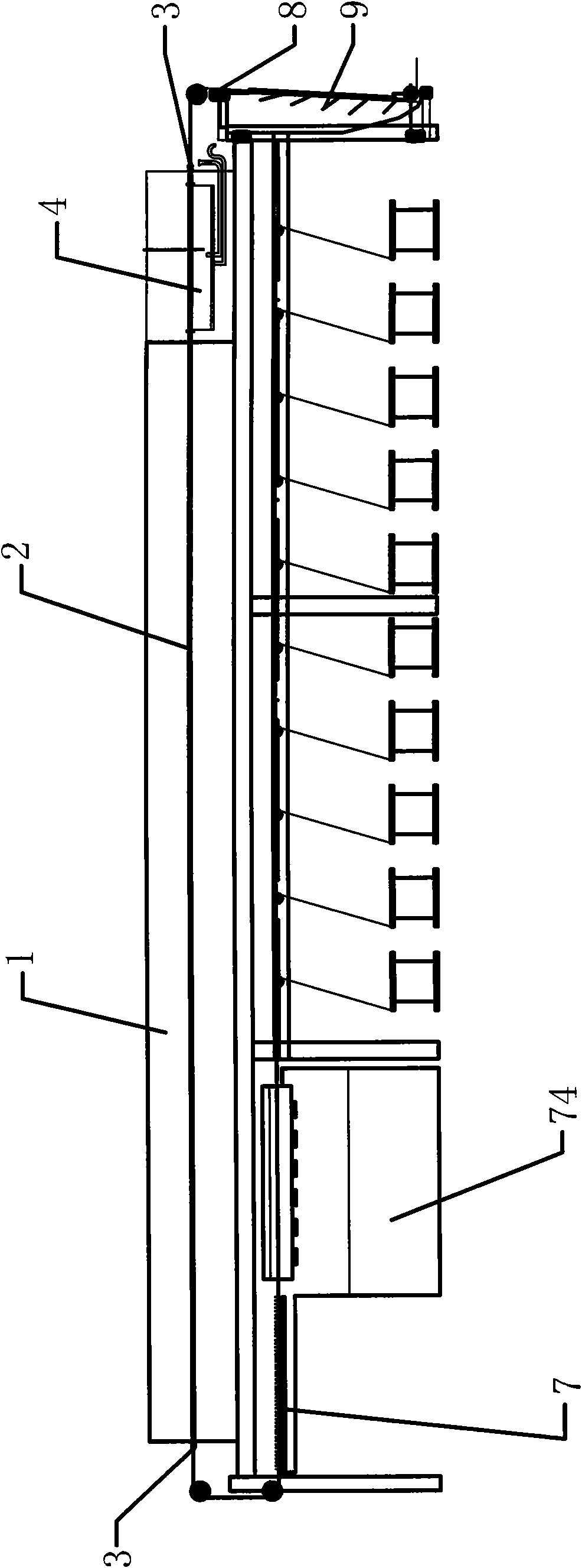
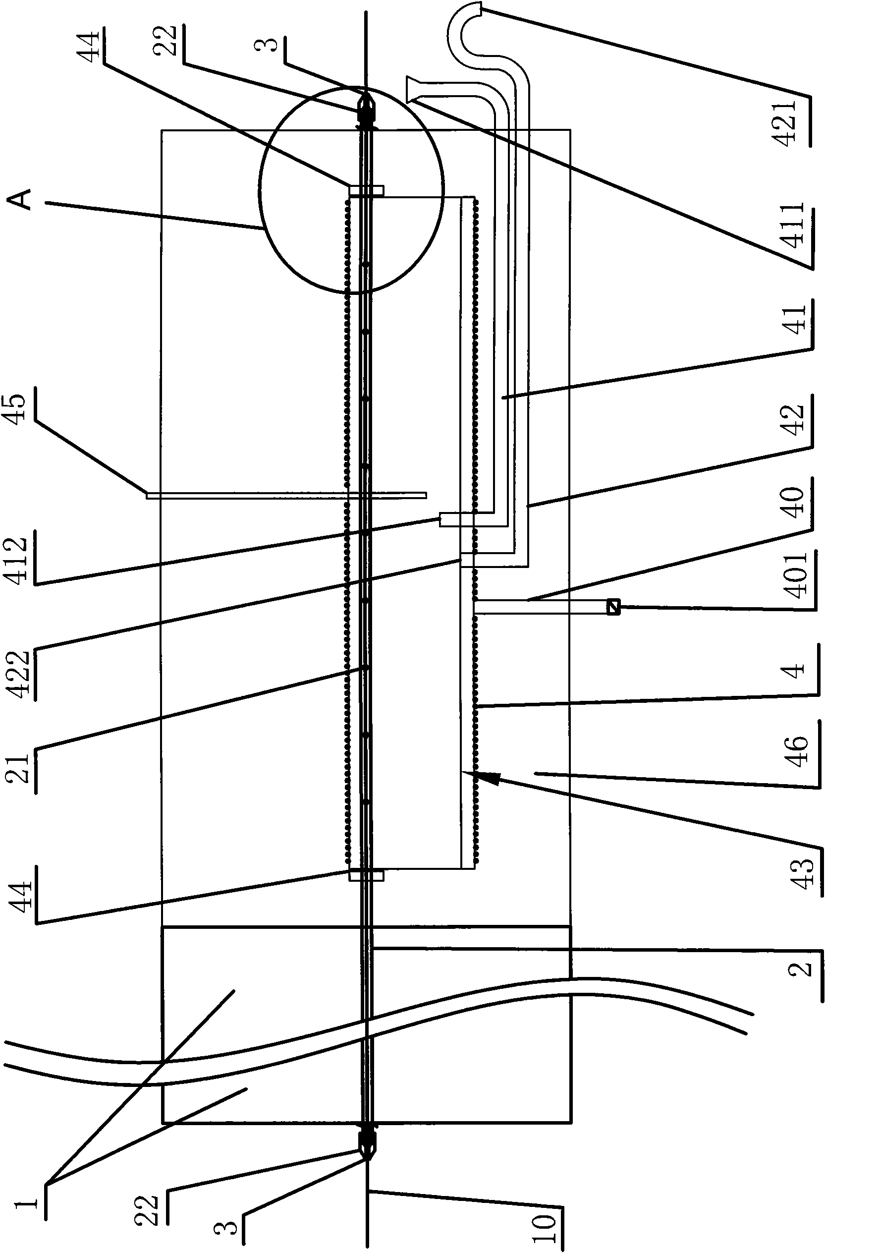
[0031] Embodiment one, such as figure 1 As shown, an energy-saving continuous annealing furnace for wire rods includes a furnace body 1 and several furnace tubes 2 for passing through wire rods 10. The furnace body 1 is placed horizontally, and several furnace tubes 2 are horizontally arranged side by side on the furnace body. 1. A built-in steam generator is installed inside the furnace body 1 close to the outlet of the furnace tube 2; the built-in steam generator includes an inner tank 4, and the furnace tube 2 passes through the inner tank 4 of the built-in steam generator , a number of steam inlets 21 are provided on the wall of the furnace tube 2 inside the liner 4; The tapered guide sleeve 22 of the nozzle and the inlet nozzle is all plugged with a small-diameter ceramic bead hole 3, and the tapered guide sleeve 22 can make the annealed wire 10 pass through the inlet nozzle and the outlet nozzle more conveniently. . The furnace body 1 is placed horizontally and the cer...

Embodiment 2

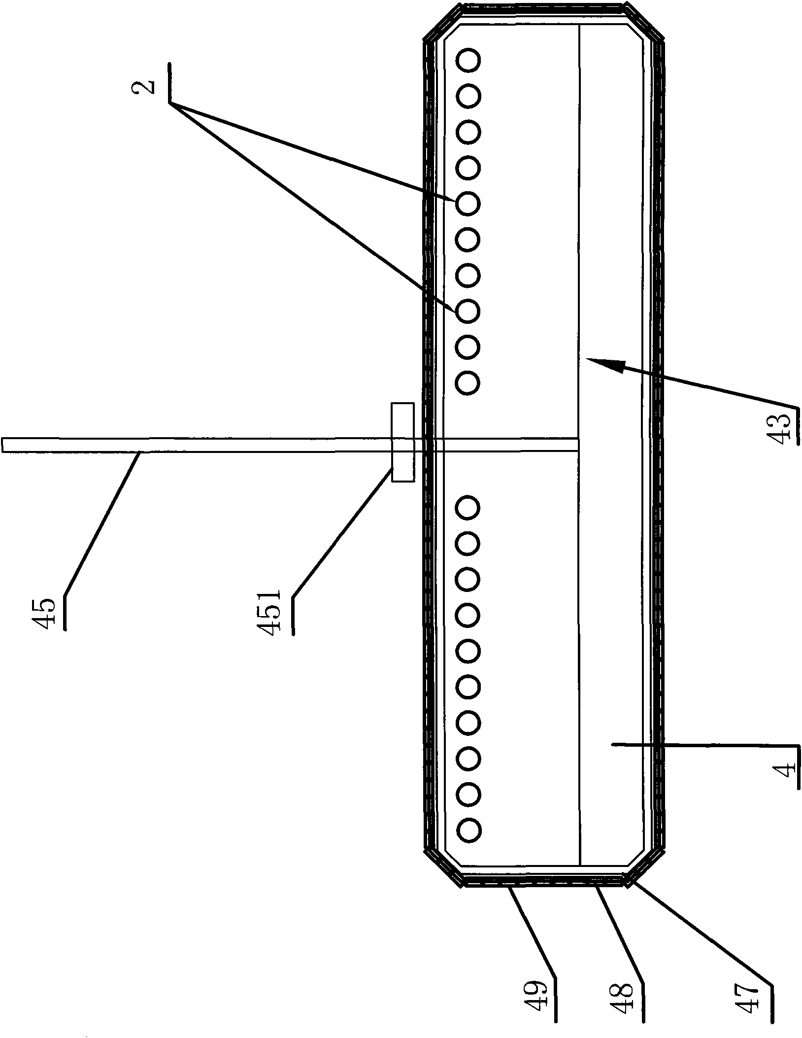
[0038] Embodiment two, such as Figure 5 to Figure 7 As shown, compared with the first embodiment, the difference of the second embodiment is that a water spray device and a water storage tank 53 are provided, while the built-in steam generator cancels the supplementary bent water pipe 41 . Specifically, the inner tank 4 of the built-in steam generator is provided with a water spray device, which is composed of a spray nozzle 51 connected to the high-pressure water pump 52 outside the furnace body 1; the spray nozzle 51 is inserted into the inner tank 4 and is close to the One end of the furnace tube 2 is provided with a number of water mist inlets 50 on the wall of the furnace tube 2 inside the inner tank 4 and close to the spray nozzle 51, and the water mist inlets 50 are larger than the steam inlet 21; The resistance wire 48 used passes through the furnace tube 2 of the inner container 4 and is close to the top of the inner container 4; The outer water overflow port 421 is...


PUM


Abstract

The invention relates to the technical field of an annealing furnace, particularly relates to an energy-saving type wire rod continuous annealing furnace, comprising a furnace body and a plurality of furnace tubes for the wire rod to pass through, the furnace body is placed horizontally, the plurality of the furnace tubes are horizontally arranged through the furnace body side by side, a built-in steam generator is arranged near the wire outlet pipe orifice of the furnace tube in the furnace body; the built-in steam generator comprises an inner container, the furnace tube passes through the inner container of the built-in steam generator, a plurality of steam inlets are arranged on the tube wall of the furnace tube in the inner container; the steam pressure of the annealing furnace in the invention is easy to control, and has high stability and reliability, and the continuous annealing furnace has good energy-saving effect, can effectively prevent the annealing wire rod from oxidizing.

Description

Technical field: [0001] The invention relates to the technical field of annealing furnaces, in particular to an energy-saving continuous annealing furnace for wire rods. Background technique: [0002] The wire continuous annealing furnace is widely used in the annealing process of enameled wire, bare copper wire and other wires. Taking enameled wire as an example, there is usually an annealing process before enameled wire is painted. The annealing process can make the enameled wire reach the necessary elongation and other mechanical properties. It can make the enameled wire have better straightness to facilitate painting. [0003] The traditional wire continuous annealing furnace can be divided into three categories: 1. The water-sealed wire continuous annealing furnace suitable for thinner wire; 2. The water-sealed horizontal wire continuous annealing furnace suitable for thicker wire; 3. Suitable for Water-sealed vertical wire continuous annealing furnace for very thick w...

Claims


Application Information

Patent Timeline
Patent Type & Authority Applications(China)
IPC IPC(8): C21D9/56C21D1/26
Inventor 周开勇
Owner 周开勇
Why Eureka
Try Eureka