
Hydraulic power machine

A power machine and hydraulic technology, applied in the direction of engine components, machines/engines, mechanical equipment, etc., can solve the problems of air, noise pollution, high cost, and failure to become power generation equipment, etc., achieve low repair rate, environmental protection and energy saving purposes, and simple structure Effect

Inactive Publication Date: 2009-12-09
罗云国
View PDF0 Cites 1 Cited by
  • Summary
  • Abstract
  • Description
  • Claims
  • Application Information

AI Technical Summary

Problems solved by technology

[0003] However, most of the backup generators (or small generators) equipped in most buildings currently use fuel oil as the energy supply to drive the engine to work, so that the generator can run normally. The traditional power generation method is not only costly, but also generates air, noise, etc. Due to the pollution problem and the mechanical loss caused by the long-term high-temperature operation of the engine, this method can only be used for short-term operation as an emergency backup power supply, and cannot be used as a power generation device that continuously supplies electric energy for a long time

Method used


Image

  • Hydraulic power machine
  • Hydraulic power machine

Examples


Embodiment 1

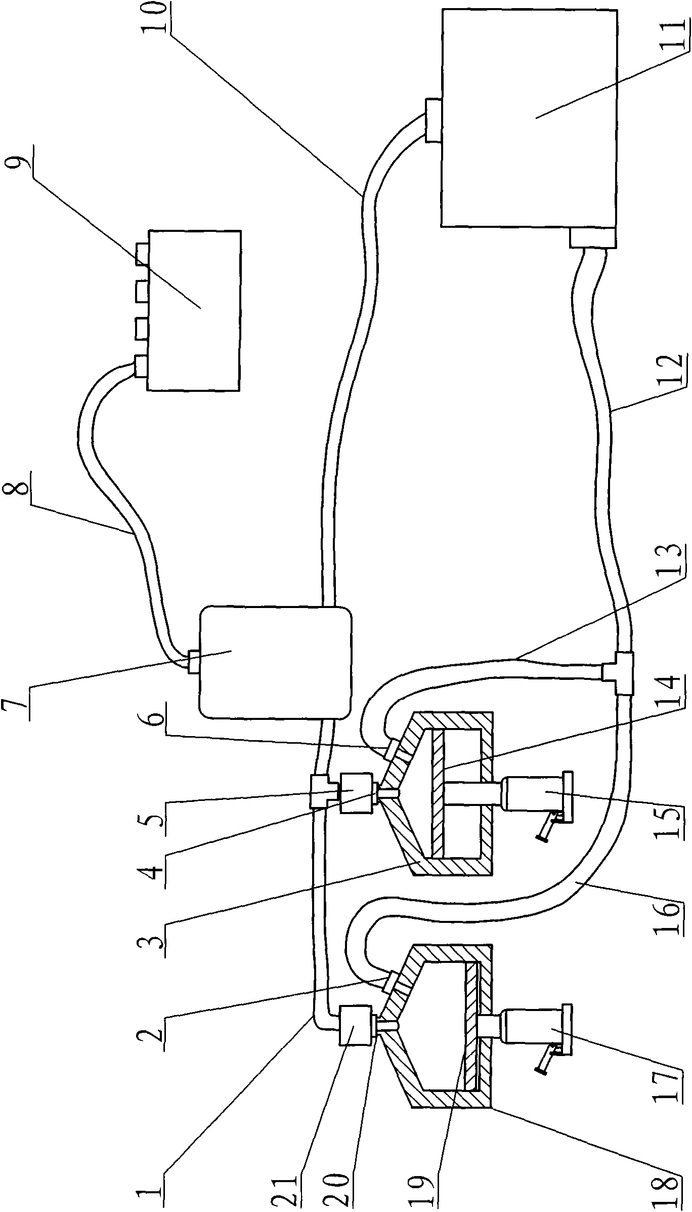
[0019] Such as figure 1 As shown, the quantity of the hydraulic cylinder of the present invention is two, and the piston in each hydraulic cylinder is all connected to the driving device, and the driving device is a jack. The jack can be a human jack, which is started by a rocker or a pedal, and is suitable for household or emergency power generation; it can also be a pneumatic jack, which is connected to an air compressor, and the air compressor drives the jack to expand and contract, which is suitable for the power supply needs of large buildings. The jack 17 is connected to the piston 19 of the hydraulic cylinder 18; the upper part of the cylinder barrel of the hydraulic cylinder 18 adopts a tapered design. This design can make the piston 19 difficult to get stuck even if it runs to the upper limit, and the repair rate is low. The output port is set on the top of the cylinder, and the input port is opened on the cone surface. A pressure reducing valve, a flow valve 21 and ...

Embodiment 2

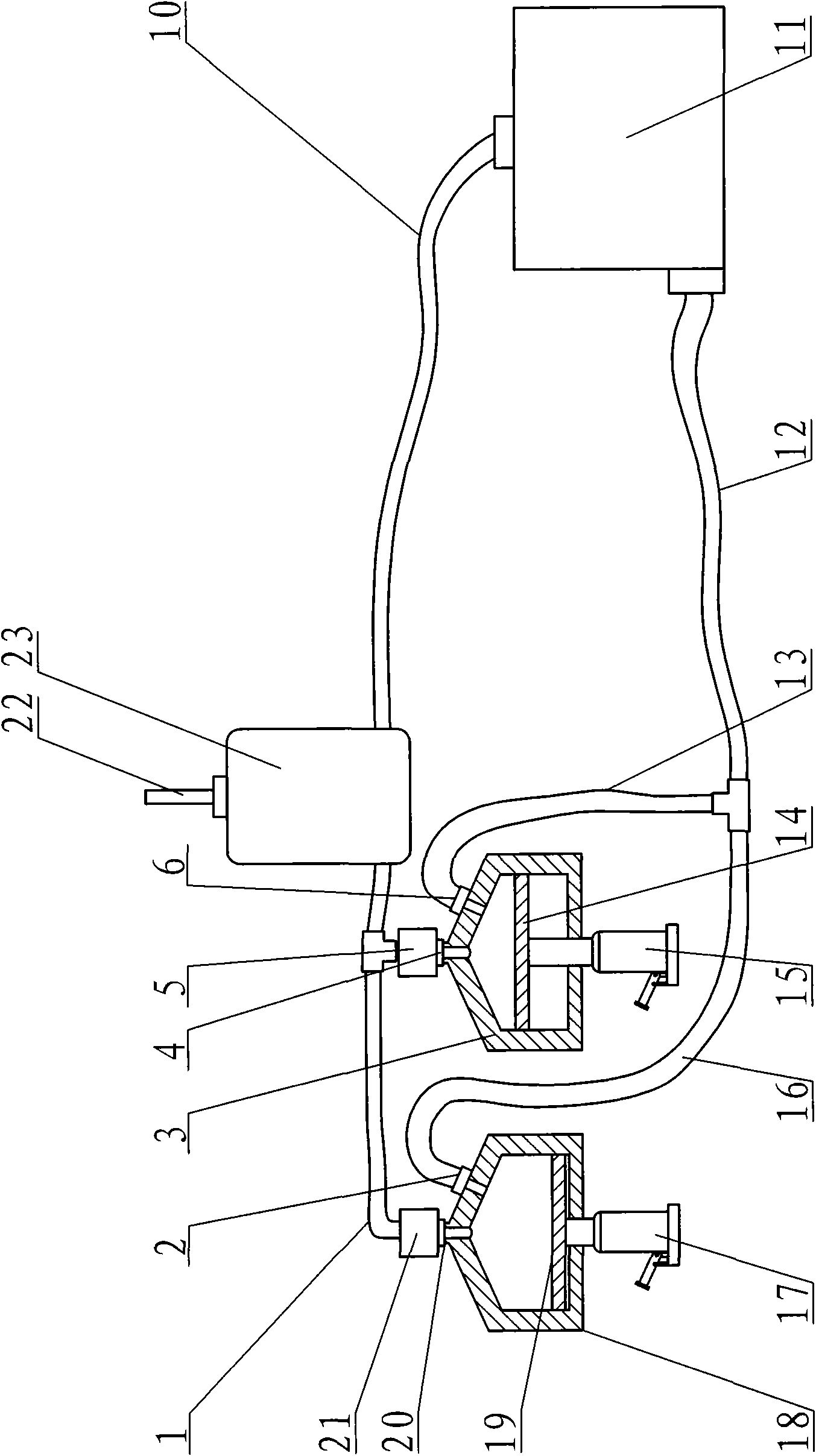
[0024] Such as figure 2 As shown, the impeller generator 7 in Embodiment 1 is replaced by an impeller transmission 23, an impeller is arranged in the impeller transmission 23, and an output shaft 22 is arranged at the center of the impeller, and the rotation of the impeller can drive the output shaft 22 to rotate and output kinetic energy.

[0025] The specific operation process is the same as that of the first embodiment, the impeller of the impeller transmission device 23 is driven by the liquid flow to rotate to generate kinetic energy, which is output through the output shaft 22 . The output shaft 22 can be connected with other devices and converted into various forms of kinetic energy.

[0026] In the present invention, the piston of the hydraulic cylinder is operated alternately up and down by controlling the jack, and the impeller in the impeller generator 7 / impeller transmission device 23 is driven to rotate by transmitting the working fluid through the infusion tube,...


PUM


Abstract

The invention relates to a hydraulic power machine, in particular to a device capable of generating electric energy and mechanical power by hydrodynamic force. The machine comprises hydraulic cylinders, an impeller type generator / transmission device, a liquid storage container and a liquid transfer pipe. The invention is characterized in that the number of the hydraulic cylinders is at least two, and a piston in each hydraulic cylinder is connected with a driving device; an inlet and an outlet are arranged on each hydraulic cylinder, the inlet on each hydraulic cylinder is communicated with the liquid storage container through the liquid transfer pipe, the outlet is connected with the impeller type generator / transmission device through the liquid transfer pipe, and the impeller type generator / transmission device is connected with the liquid storage container through the liquid transfer pipe; a one-way valve is arranged at the outlet of each hydraulic cylinder and is alternately opened and closed; a check valve is arranged at the inlet of each hydraulic cylinder and is alternately opened and closed; and the driving device is alternately driven. The invention utilizes energy conversion to achieve the purpose of generating electricity or outputting mechanical power and is an electric energy / mechanical power supplying system without energy inflammation, nuisance or pollution.

Description

technical field [0001] The invention belongs to the field of energy supply devices, and in particular relates to a device for generating electric energy and mechanical power by using liquid power. Background technique [0002] Throughout the world's energy demand and supply trends, domestic and foreign forms and operating environments have changed significantly. In order to adapt to the development of the global energy market and solve the pollution problems caused by excessive energy development and improper use, the government is currently vigorously advocating distributed and clean power generation The purpose of technology research and development and application is to disperse the power generation system at the end of use across the country, which is different from the existing large-scale centralized thermal power generation or nuclear power generation mode, and to overcome the problems caused by the popularization and construction of small distributed power systems. I...

Claims


Application Information

Patent Timeline
Patent Type & Authority Applications(China)
IPC IPC(8): F03B13/00
Inventor 罗云国郭秀丽
Owner 罗云国
Learn More