Supercharge Your Innovation With Domain-Expert AI Agents!

Drill pipe twisting device

A technology for drill pipes and translational devices, which is applied in the direction of transmission devices, mechanical control devices, gear transmissions, etc., can solve the problems of large helix angle changes, uneven longitudinal torsion of drill pipes, and low precision, and achieve uniform longitudinal torsion, The effect of compact structure and large transmission torque

Active Publication Date: 2011-12-07
ZHUZHOU CEMENTED CARBIDE CUTTING TOOLS CO LTD +1
View PDF0 Cites 0 Cited by
  • Summary
  • Abstract
  • Description
  • Claims
  • Application Information

AI Technical Summary

Problems solved by technology

However, the existing twist drill production process for obtaining helical double oil holes usually applies torque directly at both ends of the drill pipe, and the resulting drill pipe has uneven longitudinal torsion, and the helix angle varies greatly in the length direction of the drill pipe. , very low accuracy

Method used


Image

  • Drill pipe twisting device
  • Drill pipe twisting device
  • Drill pipe twisting device

Examples


Embodiment Construction

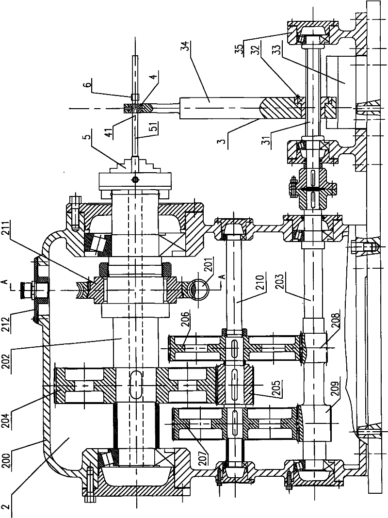
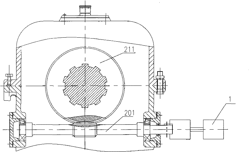
[0033] Such as figure 1 and figure 2 As shown, the drill rod twisting device of the present invention includes a driving motor 1, a transmission device 2, a translation device 3, a screw die 4, a chuck 5 and a heating coil 6, and the transmission device 2 is provided with a worm input shaft 201, a first output shaft 202 and the second output shaft 203. The driving motor 1 is connected to the worm input shaft 201 through a coupling. In this embodiment, in order to make the output speed of the driving motor 1 meet the required requirements, a frequency conversion speed regulation part is installed between the driving motor 1 and the coupling; The chuck 5 is installed on the end of the first output shaft 202, and the chuck 5 is used to clamp the drill pipe and apply torque to one end of the drill pipe; the translation device 3 is connected with the second output shaft 203, and the translation device 3 passes through the second output shaft. The shaft 203 is driven; the screw m...


PUM


Abstract

The invention discloses a drill rod torsion device, which comprises a driving motor, a transmission device, a translation device, a chuck used for clamping the drill rod, and a heating coil wound on the drill rod, wherein the transmission device is provided with a first output shaft and a second output shaft, the driving motor is connected with the translation device, the chuck is arranged at the end part of the first output shaft, the translation device is connected with the second output shaft, the translation device thereon is provided with a spiral mold which is arranged between the chuck and the heating coil, and the central line of the spiral mold and the rotation axis of the chuck are coaxially arranged along the translational direction of the translation device. The drill rod torsion device has the advantages of simple structure, capability of uniform torsion and high precision of torsion shaping.

Description

technical field [0001] The invention relates to twist drill manufacturing equipment, in particular to a drill pipe twisting device. Background technique [0002] In the machining industry, a drill bit is a tool that is often used, and the most commonly used one is a twist drill. In order to improve the drilling performance and service life of twist drills, in addition to heat treatment, surface titanium plating, polishing, and nitriding, improving the cooling method has become a problem that cannot be ignored. Traditional twist drills must be directly sprayed with coolant during the cutting process. On the drill bit, when the drilling depth reaches 30 mm, the cooling is extremely insufficient, and the cutting edge of the drill bit is hardly cooled. In order to make the drill bit work normally, the operator must withdraw the drill bit frequently and continue drilling after cooling down, so the cutting speed is slow, the efficiency is low, the drill bit wears quickly, the lif...

Claims


Application Information

Patent Timeline
Patent Type & Authority Patents(China)
IPC IPC(8): B21C23/14B21C25/02B21C29/00F16H3/08F16H63/32F16H57/02F16H57/023F16H57/039
Inventor 何云王社权苏红娟汤爱民李屏
Owner ZHUZHOU CEMENTED CARBIDE CUTTING TOOLS CO LTD
Features
  • R&D
  • Intellectual Property
  • Life Sciences
  • Materials
  • Tech Scout
  • Unparalleled Data Quality
  • Higher Quality Content
  • 60% Fewer Hallucinations
Learn More