
Indexable insert for milling, milling cutter and method for mounting milling cutter

A technology of indexing inserts and milling tools, which is applied in the field of milling, and can solve problems such as difficult installation and management of inserts, too many grooves, and easy chipping of cutting inserts, etc., to achieve good chip removal performance, reduce wear, and disperse cutting hot effect

Active Publication Date: 2010-10-06
ZHUZHOU CEMENTED CARBIDE CUTTING TOOLS CO LTD
View PDF1 Cites 2 Cited by
  • Summary
  • Abstract
  • Description
  • Claims
  • Application Information

AI Technical Summary

Problems solved by technology

However, this kind of insert also has disadvantages: when milling, two different types of inserts must be used. When these two inserts are installed on the cutter body, it is required to form a complementary shape between the grooves of the wave-shaped cutting edges of the two inserts. , which puts forward relatively high requirements on the manufacturing precision and installation precision of the blade, which brings certain difficulties to the installation and management of the blade, and increases the processing cost at the same time.
In addition, since only two cutting edges are available for this type of insert, the number of grooves should not be too large, otherwise the strength of the cutting edge will be greatly reduced, which will lead to problems such as chipping of the cutting edge
The strength of the divided cutting edge will be greatly reduced, so there is a problem that the cutting insert is prone to chipping
Moreover, the advantages of this structure cannot be reflected in small depth of cut, which reduces its application range

Method used


Image

  • Indexable insert for milling, milling cutter and method for mounting milling cutter
  • Indexable insert for milling, milling cutter and method for mounting milling cutter
  • Indexable insert for milling, milling cutter and method for mounting milling cutter

Examples


Embodiment 1

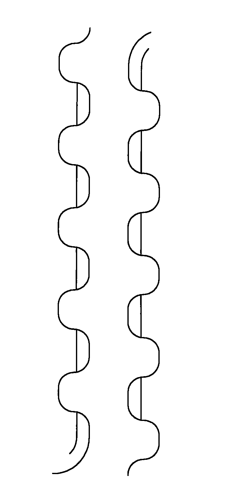
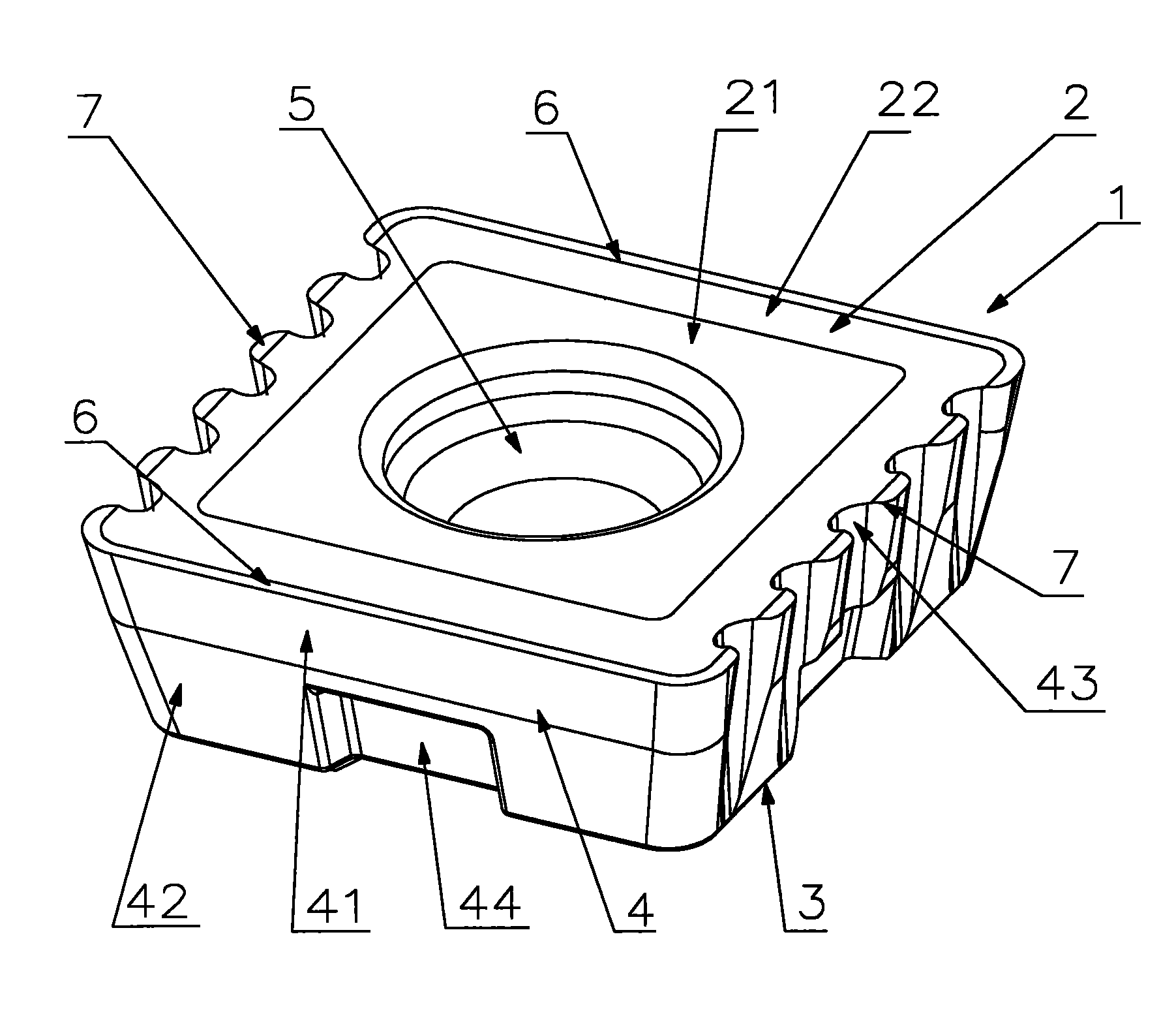
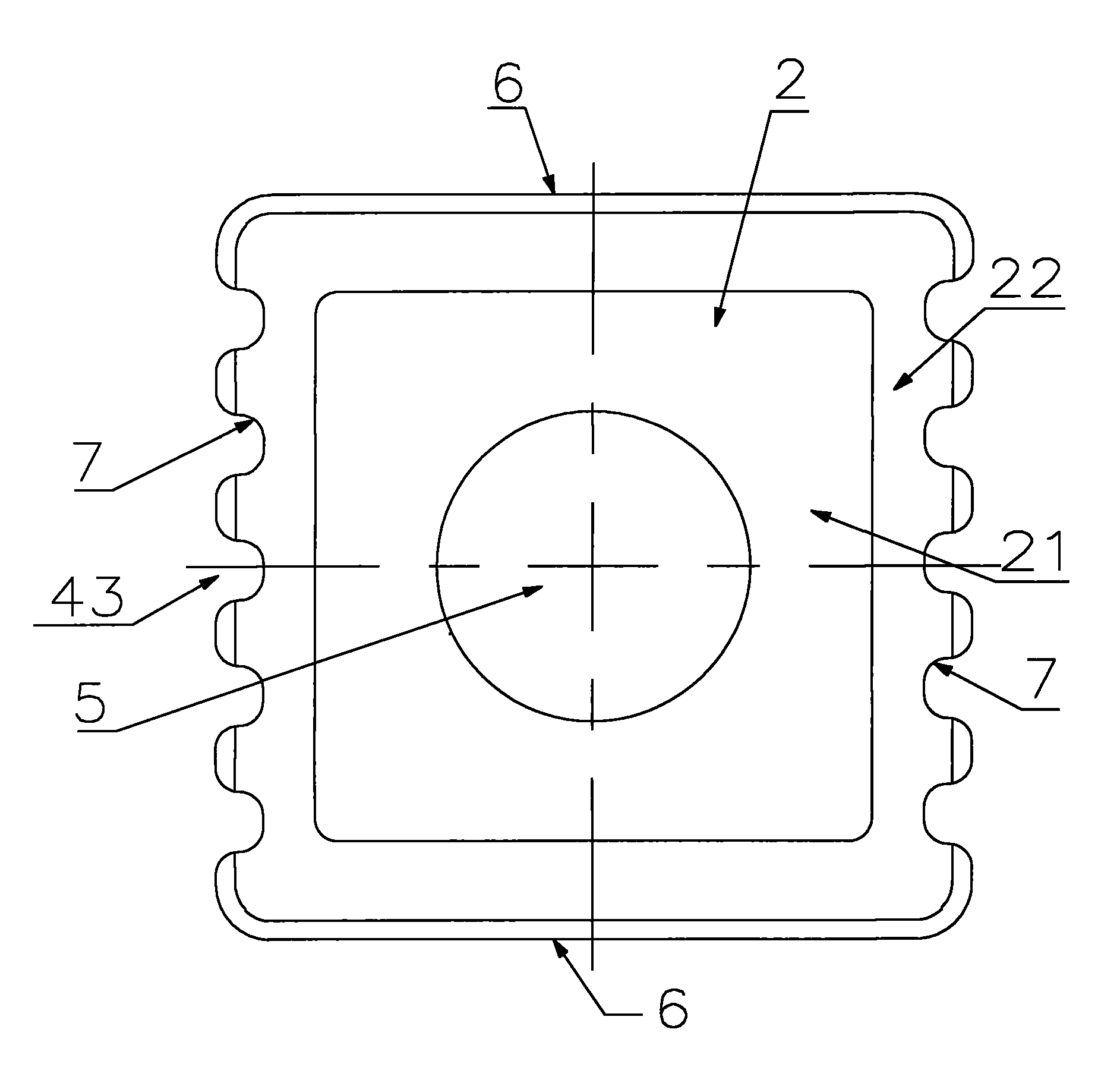
[0033] Embodiment 1: as Figure 2 to Figure 5 As shown, the indexable insert for milling of the present invention includes a polygonal plate-shaped insert body 1, and the insert body 1 is surrounded by an upper surface 2, a lower surface 3, and a plurality of sides 4 connecting the upper and lower surfaces. The center of the blade body 1 is provided with a blade center hole 5 for installation and positioning. The upper surface 2 includes a support surface 21 and a rake surface 22, the rake surface 22 is located at the periphery of the support surface 21, each side 4 has a relief surface 41 and a relief surface 42, the relief surface 41 intersects the rake surface 22, and the rear The clearance surface 42 intersects the lower surface 3, the flank 41 of one of the adjacent two sides 4 intersects with the rake face 22 to form a straight edge 6, and the flank 41 of the other side 4 intersects with the rake face 22 to form Wave blade 7, the waveform of the wave blade 7 is arc-shap...

Embodiment 2

[0034] Embodiment 2: as Figure 9 As shown, the milling tool of the present invention includes a tool body 10, six blade holders 8 are arranged at equal intervals along the circumferential direction on the cutter body 10, and the milling tool in Embodiment 1 is fixed on each blade holder 8 by a compression screw 11. For the indexable insert, the linear edge 6 and the wave-shaped edge 7 of the indexable insert for milling installed on the adjacent insert seat 8 are arranged alternately. This structure improves the cutting resistance when all the main cutting edges are straight long edges. , high cutting temperature, unsatisfactory chip breaking performance, etc., and also avoid the problem of complementary connection error when the main cutting edge is a pair of complementary wave-shaped interrupted edges, so that the processing quality of the workpiece surface is improved, and there is The ability to reduce and disperse resistance, resist vibration of the knife, reduce the pre...


PUM


Abstract

The invention discloses an indexable insert for milling, a milling cutter and a method for mounting the milling cutter, the indexable insert for milling comprises an insert body which is surrounded by an upper surface, a lower surface and side surfaces connected with the upper surface and the lower surface as well as which is provided with an insert central hole, the upper surface is provided with a front cutter face, each side surface has a rear cutter face and a rear gap face, the rear cutter face intersects the front cutter face, the rear gap face intersects the lower surface, the rear cutter face and the front cutter face of one of two adjacent side surfaces are intersected to form a straight edge, the rear cutter face and the front cutter face of the other one are intersected to forma waveform edge, and the indexable insert has the advantage of achieving high-effective processing in case of large cutting depth and large cutting feed. The cutter body is provided with more than two tool posts by the milling cutter, the indexable insert for milling is mounted on the tool posts of the milling cutter via the mounting method so that the straight edges and the waveform edges of theadjacent indexable inserts for milling are distributed alternatively, and the milling cutter has the advantages of convenient mounting, being capable of improving processing quality on the surface ofworkpiece and good economical efficiency.

Description

technical field [0001] The invention relates to milling processing technology, in particular to an indexable insert for milling, a milling cutter equipped with the insert and a milling cutter installation method. Background technique [0002] In the process of milling, the surface quality of the workpiece and the wear of the blade are often considered more, while the force of the tool is rarely considered, and most of them are carried out with continuous straight edge or wave edge and wave edge. processing. For the continuous straight edge, since the entire cutting edge is involved in the cutting process, the cutting resistance of the blade is very large, and the long-term continuous relative motion between the blade and the workpiece will also generate more cutting heat. The machining is intermittent, and there is a strong impact force during the machining process. These factors lead to excessive wear or damage of the blade, especially in the case of high feed and large de...

Claims


Application Information

Patent Timeline
Patent Type & Authority Patents(China)
IPC IPC(8): B23C5/08B23P19/04
Inventor 刘敏江爱胜刘志林李文学
Owner ZHUZHOU CEMENTED CARBIDE CUTTING TOOLS CO LTD
Learn More