Unlock instant, AI-driven research and patent intelligence for your innovation.

Vertical takeoff and landing aircraft

A vertical take-off and landing aircraft and vertical tail technology, applied in the field of aircraft, can solve the problems of increasing engine power, large rotor diameter, large fuel consumption, etc., and achieve the effect of increasing power, improving use efficiency, and simple and reliable structure

Inactive Publication Date: 2009-12-16
张庆柳
View PDF0 Cites 14 Cited by
  • Summary
  • Abstract
  • Description
  • Claims
  • Application Information

AI Technical Summary

Problems solved by technology

But there are also many major disadvantages at the same time. Due to the large diameter of the rotor, the speed of the tilting rotorcraft can only be within 400 km / h in level flight. The take-off weight of the aircraft can only be 83%-85% of the thrust of the engine, which greatly limits the payload of the aircraft and affects the fuel capacity and flight range of the aircraft. The amount of fuel is huge, which limits the combat radius of the aircraft. However, the F-35 developed by Lockheed Martin of the United States uses a lift fan and a short take-off / vertical landing with a steering vector nozzle. Due to the lift fan and the steering vector nozzle The lift generated by the tube is not enough to enable the aircraft to achieve vertical take-off and landing, so it can only be changed to short take-off / vertical take-off and landing, which greatly reduces the maneuverability of the aircraft, and it is difficult to greatly increase the engine power under the current technical conditions

Method used


Image

  • Vertical takeoff and landing aircraft
  • Vertical takeoff and landing aircraft
  • Vertical takeoff and landing aircraft

Examples


Embodiment Construction

[0017] The present invention will be further described below in conjunction with the accompanying drawings.

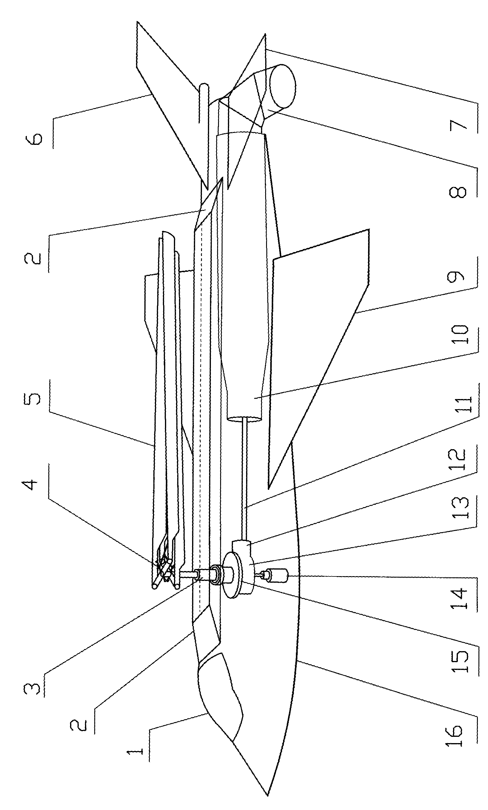
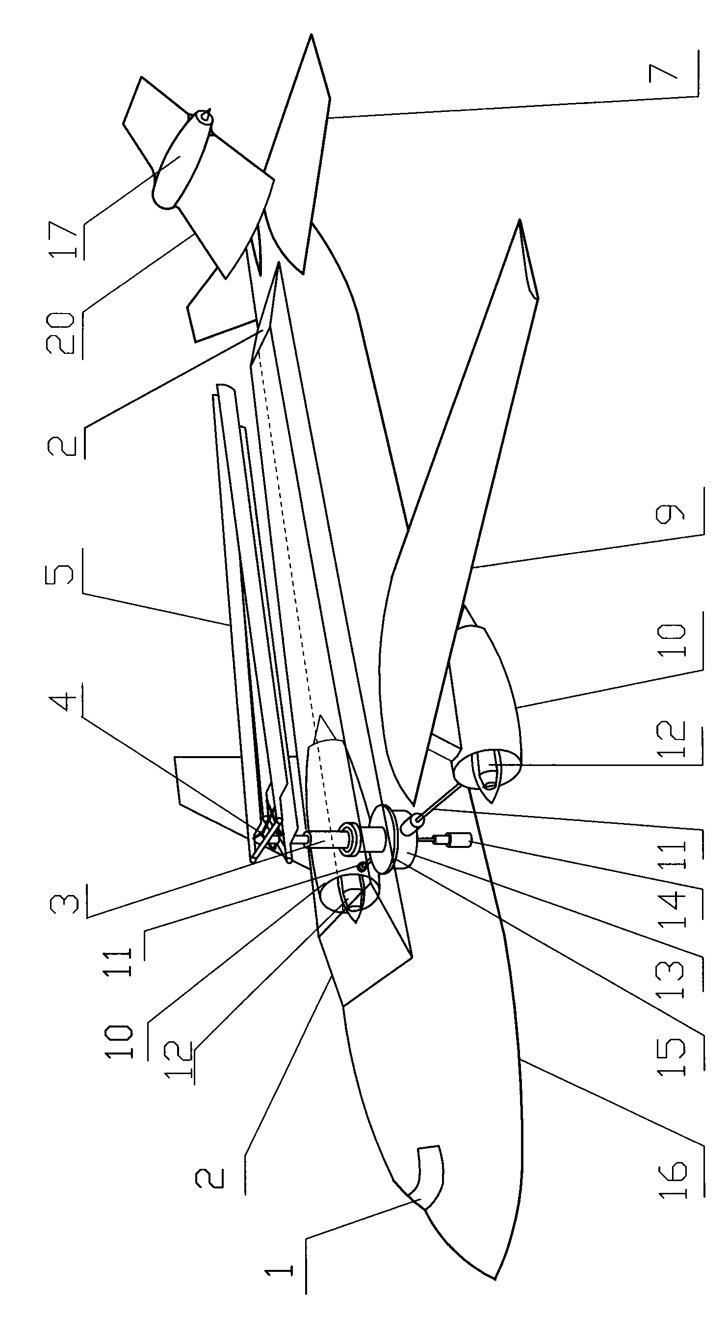
[0018] exist figure 1 Among them, the vertical take-off and landing aircraft is made of cockpit 1, fuselage 16, aeroengine 10, wing 9, horizontal tail 7, vertical tail 6 and control system, and rotor 5 is equipped with on the fuselage 16 top, and rotor 5 is equipped with rotor automatic Positioning device 4, rotor 5 is connected with rotor shaft 3, rotor shaft 3 is connected with speed reducer 13, rotor shaft telescopic device 14, rotor shaft automatic positioning device 15 is housed on rotor shaft 3, the rotor that can open and close is equipped with on the top of fuselage 16 Cabin 2, aeroengine 10 is connected with speed reducer 13 through transmission shaft 11, clutch 12, and aeroengine 10 rear portion is equipped with steering vector tail nozzle 8. The profile design of aircraft is basically similar to common aircraft design, and the rotor compartment 2 that can b...


PUM


Abstract

The invention discloses a vertical takeoff and landing aircraft and aims at providing a vertical takeoff and landing aircraft which has simple structure can be manufactured easily, and can take off and land vertically and fly flat at high speed without greatly increasing aeroengine power additionally. The vertical takeoff and landing aircraft comprises a cockpit, a fuselage, aeroengines, wings, stabilizers, a vertical tail and a control system, wherein the upper part of the fuselage is provided with rotor wings, automatic positioning devices of the rotor wings are arranged on the rotor wings, the rotor wings are connected with rotor wing shafts which are connected with speed reducers and telescopic devices of the rotor wing shafts, automatic positioning devices of the rotor wing shafts are arranged on the rotor wing shafts, rotor wing cabins which can be opened and closed are arranged at the top of the fuselage, the aeroengines are connected with the speed reducers through transmission shafts and clutches, and a steering vector jet nozzle is arranged at the rear parts of the aeroengines. When the vertical takeoff and landing aircraft takes off and lands vertically, the rotor wing cabins open, and the rotor wings and the rotor wing shafts extend out of the rotor wing cabins. When the vertical takeoff and landing aircraft flies flat, the rotor wings and the rotor wing shafts retract to the rotor wing cabins and the rotor wing cabins are closed. The invention has the main purpose of providing the vertical takeoff and landing aircraft which can take off and land vertically and can fly flat at high speed.

Description

technical field [0001] The invention belongs to an aircraft, more specifically, it relates to a vertical take-off and landing aircraft. Background technique [0002] So far, five types of vertical take-off and landing aircraft have been developed successively: tail seat type, tilting power device type, thrust steering type, special lift power device type and the mixed configuration type of the last three types, typical representatives such as the Boeing Company of the United States V-22 tilt rotor aircraft, British "Harrier" deflecting nozzle vertical take-off and landing aircraft, American Lockheed Martin F-35 uses lift fan and afterburning turbofan engine with steering vectoring nozzle short takeoff / vertical landing aircraft. The above-mentioned vertical take-off and landing, short-moment take-off / vertical landing aircraft have all been put into use. Since they do not need special airports and runways, they have a better effect in increasing maneuverability and flexibilit...

Claims


Application Information

Patent Timeline
IPC IPC(8): B64C27/06B64C27/08B64C27/12B64C27/22B64D35/02B64D35/08
CPCB64C27/08B64C27/30
Inventor 张庆柳
Owner 张庆柳
Features
  • R&D
  • Intellectual Property
  • Life Sciences
  • Materials
  • Tech Scout
  • Unparalleled Data Quality
  • Higher Quality Content
  • 60% Fewer Hallucinations
Learn More