

Optical package, method of manufacturing the same, backlight, and liquid crystal display
A packaging and optical technology, applied in chemical instruments and methods, optics, optical components, etc., can solve the problem of increasing the thickness of lighting devices, and achieve the effect of preventing wrinkles and realizing thickness.
- Summary
- Abstract
- Description
- Claims
- Application Information
AI Technical Summary
Problems solved by technology
Method used
Image

Examples
no. 1 approach
[0059] (1-1) Structure of liquid crystal display
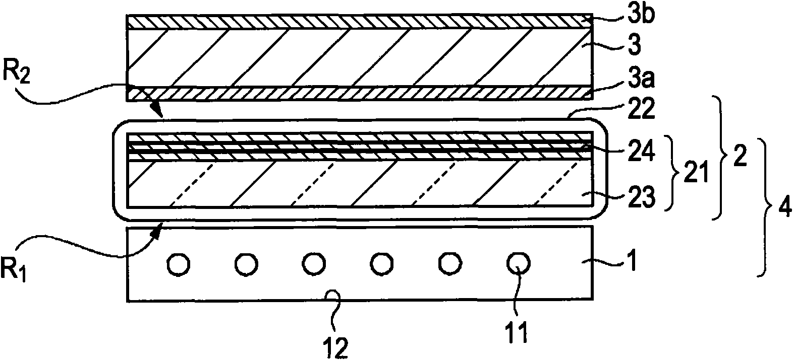
[0060] figure 1 It is a schematic diagram showing a structural example of the liquid crystal display according to the first embodiment of the present invention. Such as figure 1 As shown, the liquid crystal display includes a lighting device 1 that emits light, an optical package 2 that transmits light emitted from the lighting device 1 and a liquid crystal panel 3 that displays images based on the light transmitted through the optical package 2. The lighting device 1 and the optical package 2 constitute a backlight 4. Hereinafter, with regard to the surface of the optical component such as the optical package 2, the surface on which the light from the lighting device 1 is incident is referred to as the "light incident surface", and the surface from which the light incident on the light incident surface is emitted is It is called the "light emitting surface", and the surface located between the light incident surface and the li...
no. 1 example
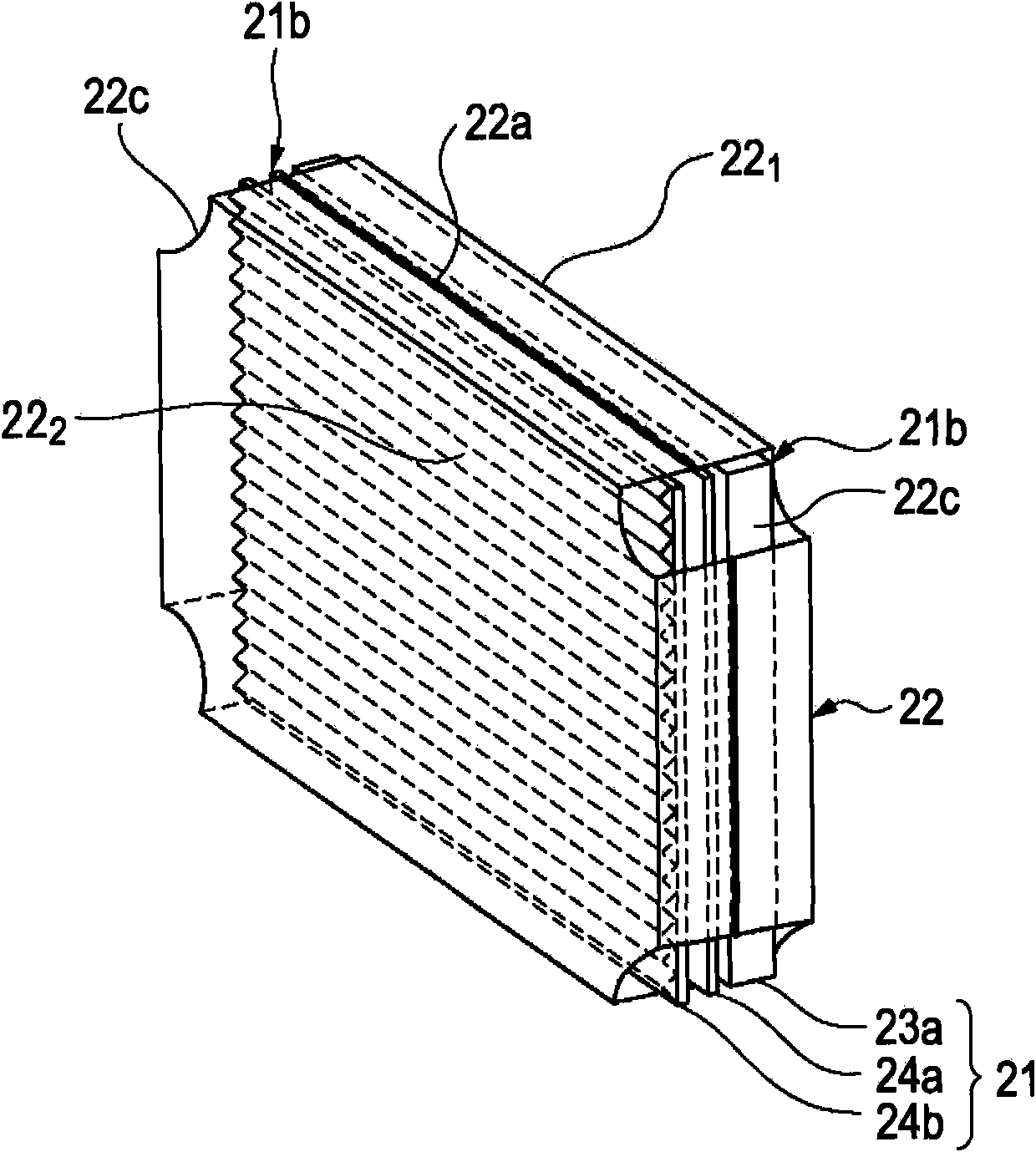
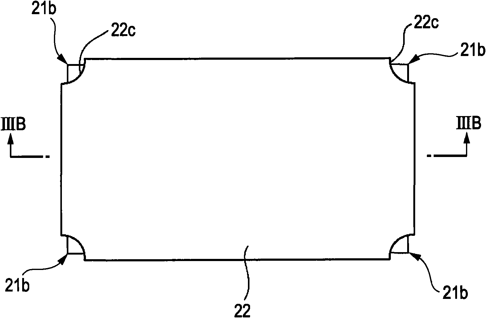
[0097] Will now refer to Figure 2 ~ Figure 5 A first example of the structure of the optical package 2 according to the first embodiment of the present invention will be described in detail. figure 2 , Figure 3A with Figure 3B A first example of the structure of the optical package according to the first embodiment of the present invention is shown. Such as figure 2 , Figure 3A with Figure 3B As shown, the optical package 2 includes, for example: a diffusion plate 23a, which is a plate-shaped support; a diffusion film 24a and a prism sheet 24b, which are film-shaped or sheet-shaped optical elements; and a packaging member 22, which covers the support And optical components, and integrate them. The packaging member 22 has a film-like or sheet-like shape. The packaging member 22 has shrinkage properties or stretch properties, and contains voids and fillers provided in the voids. In this example, the diffusion plate 23a, the diffusion film 24a, and the prism sheet 24b constitu...
no. 3 approach
[0166] Figure 24 An example of the structure of a liquid crystal display according to the third embodiment of the present invention is shown. The difference between the liquid crystal display and the first embodiment is that the illuminating device 1 includes a supporting portion 35 that supports the optical package 2, and the optical package 2 includes a portion to be supported that is engaged with the supporting portion 35 of the illuminating device 1 36.
[0167] Figure 25A with Figure 25B An example of the structure of the backlight according to the third embodiment of the present invention is shown. The backlight includes one or more light sources 11, a backlight chassis 34 and an optical package 2 supported by the backlight chassis 34. The optical package 2 includes one or more parts 36 to be supported. The portion 36 to be supported is preferably provided on the outer periphery of the optical package 2, and is preferably provided at a position exposed at the opening 22...
PUM
| Property | Measurement | Unit |
|---|---|---|
| thickness | aaaaa | aaaaa |
| thickness | aaaaa | aaaaa |
| thickness | aaaaa | aaaaa |
Abstract
Description
Claims
Application Information