Motion estimation in treatment planning

A technology of motion and motion model, applied in the field of motion estimation, can solve the problem of harmfulness of healthy tissue

Inactive Publication Date: 2009-12-23
KONINKLIJKE PHILIPS ELECTRONICS NV
View PDF4 Cites 12 Cited by
  • Summary
  • Abstract
  • Description
  • Claims
  • Application Information

AI Technical Summary

Problems solved by technology

Regrettably, however, such an approach is detrimental to healthy tissue in other ways
Moreover, such motion als...

Method used


Image

  • Motion estimation in treatment planning
  • Motion estimation in treatment planning
  • Motion estimation in treatment planning

Examples


Embodiment Construction

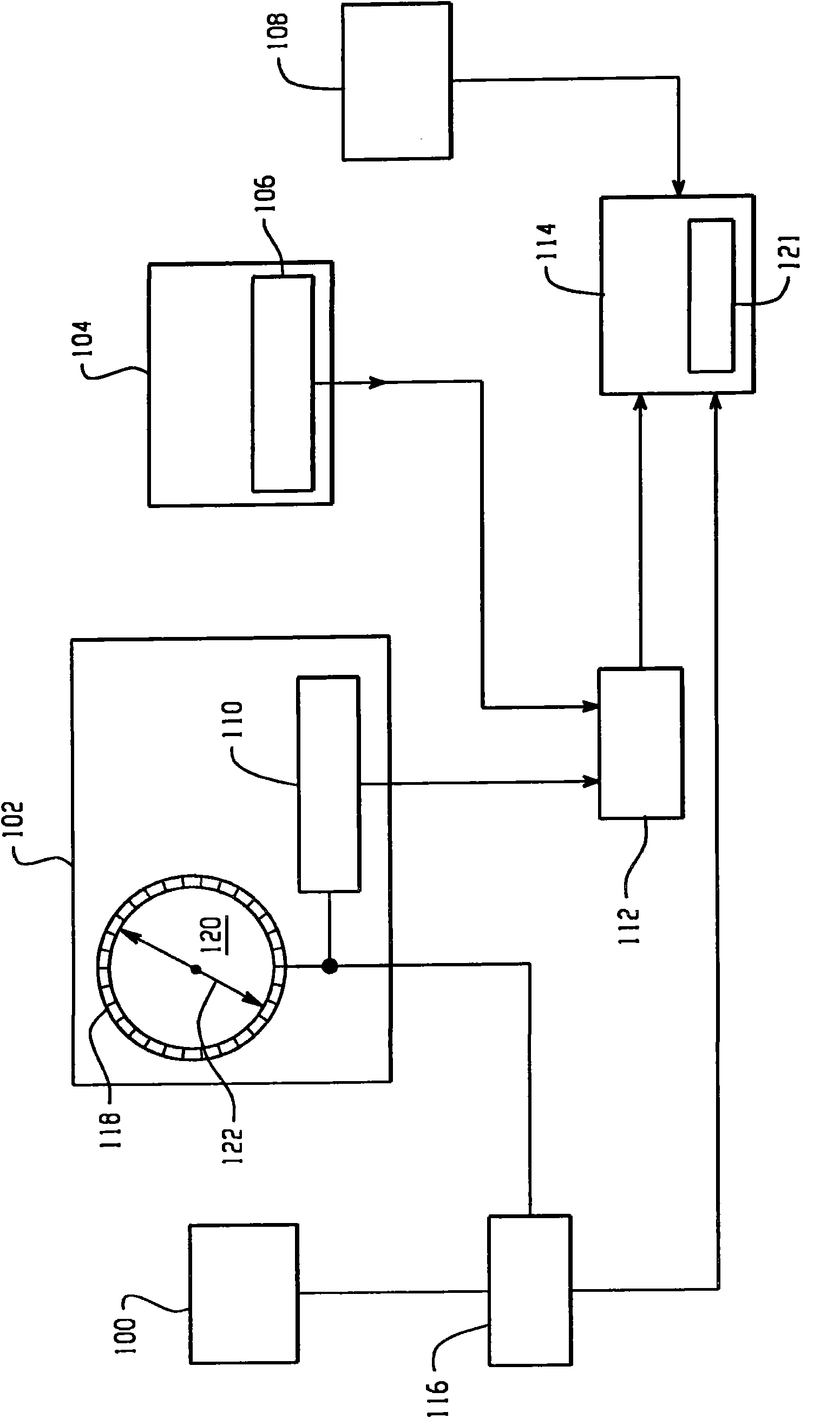
[0021] refer to figure 1 , system 100 includes functional imaging modality scanner 102 , structural imaging modality scanner 104 , motion monitor 100 , scanning motion modeler 116 , and treatment planner 112 .

[0022] Such as figure 1 As shown in , the functional imaging modality scanner 102 is a PET scanner. PET scanners conventionally include a plurality of radiation-sensitive detectors 118 disposed in a generally annular or cylindrical arrangement around an examination region 120 . In conjunction with PET examinations, tracers including positron-emitting radionuclides are introduced into the subject under examination. As the radionuclide decays, the emitted positrons interact with electrons in a process known as positron annihilation, which simultaneously generates pairs of time-coincident 511 kiloelectronvolt (keV) gamma rays that Travel along line of response (LOR) 122 in substantially the opposite direction. Where the imager 102 is a time-of-flight (TOF) PET scanner...


PUM


Abstract

An apparatus includes a scanner (102, 104) and a scanning motion monitor (100). A motion modeler (116) uses data from the scanning motion monitor (100) and the scanner (102, 104) to generate a motion model which describes motion of a region of interest of an object. A treatment planner (112) uses image data from the scanner (102, 104) to establish a treatment plan for the object. A treatment device (114), which operates in conjunction with a treatment motion monitor (108), uses the motion model to compensate for motion of the object during application of the treatment.

Description

technical field [0001] This application is concerned with motion estimation in therapy and treatment planning. Although it is particularly used in medicine to estimate motion using positron emission tomography (PET) data in conjunction with external radiation therapy, it is also relevant to other applications where it is desired to compensate for the effects of object motion. Background technique [0002] In medical applications, structural medical imaging modalities such as computed tomography (CT) and magnetic resonance (MR) are widely used to generate image data indicative of the internal morphology of a patient. One application of this data is radiation therapy planning (RTP) in oncology, where image data is used to calculate a spatially varying radiation dose to be applied to a tumor or other lesion. The calculated dose is delivered to the patient using a treatment technique such as Intensity Modulated Radiation Therapy (IMRT). These techniques are used to tailor ther...

Claims


Application Information

Patent Timeline
IPC IPC(8): A61B6/03
CPCA61B6/527A61B6/037A61B5/055A61N5/1067A61N5/1037A61B5/721A61B5/7289A61N2005/1052A61N5/103A61B6/032
Inventor R·布林克斯C·迈尔A·菲舍D·加尼翁M·布施
Owner KONINKLIJKE PHILIPS ELECTRONICS NV
Why Eureka
Try Eureka