Method for selective hydrogenation and separation for pyrolysis gas

A technology for selective hydrogenation and cracking of gas, which is applied in the field of selective hydrogenation of alkynes and dienes, which can solve the problems of limited hydrogen, increased energy consumption, and reduced activity of polymerization catalysts, so as to improve selectivity and safety and reduce energy consumption. consumption and equipment size, and the effect of reducing the number of reaction devices

Active Publication Date: 2009-12-30
CHINA PETROLEUM & CHEM CORP +1
View PDF21 Cites 12 Cited by
  • Summary
  • Abstract
  • Description
  • Claims
  • Application Information

AI Technical Summary

Problems solved by technology

The shortcoming of this patent is: 1, because this patent application places the mixed-phase hydrogenation reactor on the downstream side of the front depropanizer, what enters the mixed-phase hydrogenation reactor is cooled and partially condensed rich in C 3 and lighter component streams, so this patented technology can only hydrogenate low-carbon alkynes in the mixed-phase hydrogenation reactor, and cannot hydrogenate high-carbon unsaturated hydrocarbons such as butyne and butadiene. Therefore, the amount of hydrogen consumed is limited, and a large amount of remaining hydrogen enters the cryogenic part of the cracked gas, resulting in high energy consumption
2. If the remaining high-carbon alkynes and dienes enter the polymerization process, the activity of the polymerization catalyst will be reduced, and the physical properties of the polymer will be deteriorated
3. Since the patent application does not carry out hydrotreating on the stream entering the front depropanizer, the alkynes and diolefins in the stream are likely

Method used


Image

  • Method for selective hydrogenation and separation for pyrolysis gas

Examples


Embodiment 1

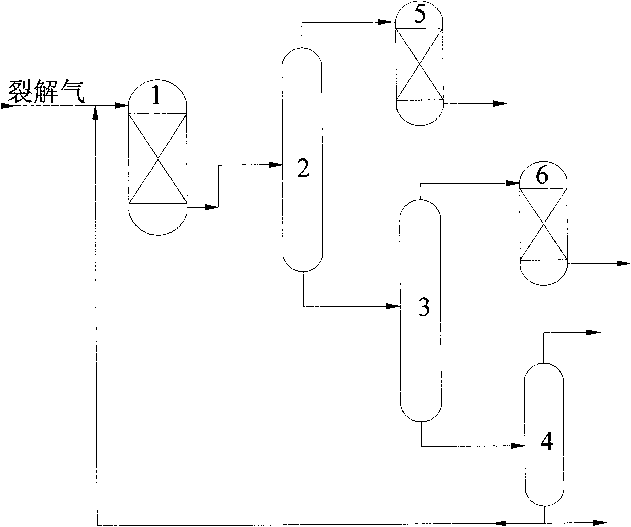
[0064] see figure 1, the gas phase raw material 1 containing olefins obtained from the steam cracking unit, the specific composition can refer to Table 1, mixed with the liquid phase flow from the bottom of the debutanizer, and then heat exchanged in the heat exchanger, enter the mixed phase Hydrogenation Reactor 1. Mixed-phase hydrogenation reactor 1 uses BC-L-83A hydrogenation catalyst (Sinopec Produced by the company Beijing Research Institute of Chemical Industry) to operate in the presence of most of the acetylene hydrogenation, such as the remaining 100ppm (mole) of acetylene, which means that the conversion rate of propyne and propadiene is about 50%, and the conversion of carbon four or more dienes The rate is about 80%. The reaction product from the mixed-phase hydrogenation reactor is cooled by a cooler and enters the front deethanizer 2, where it is separated into a liquid phase flow and a gas phase flow, and the gas phase flow enters the carbon two front hydrogen...


PUM


Abstract

The invention discloses a method for selective hydrogenation and separation for pyrolysis gas, and belongs to the technical field of selective hydrogenation of unsaturated hydrocarbon. In order to solve the problems existing in the prior art that the liquid flow of a mixed phase hydrogenation reactor contains a large number of C3 and C4 components, cannot fully play a role in flushing in the reactor and repeatedly enters a front-end deethanization tower to cause high energy consumption, large equipment size, high operation cost and disadvantage to improve C3 selectivity and the like, the invention provides the method for selective hydrogenation for C2-C10 high unsaturated hydrocarbon (alkyne and diolefin) by using material flow at the bottom of the deethanization tower as liquid flow at the upstream side of the front-end deethanization tower of an olefin production device. The method enables the liquid flow of the mixed phase hydrogenation reactor to fully come into play, reduces the charging amount entering the front-end deethanization tower and energy consumption and equipment investment, and is favorable for improving the selectivity.

Description

technical field [0001] The present invention relates to a method for the selective hydrogenation of alkynes and dienes, more specifically, the present invention relates to a method for the selective hydrogenation of alkynes and dienes in cracked gas from an olefin production unit. Background technique [0002] Unless otherwise specified, the highly unsaturated hydrocarbons mentioned in the present invention refer to hydrocarbons containing triple bonds or two double bonds. [0003] Processes for the conversion of hydrocarbons at high temperatures, such as steam thermal cracking or catalytic cracking, can provide unsaturated hydrocarbons, such as ethylene, acetylene, propylene, butadiene, butene; saturated alkanes, such as ethane, propane, butane; There are also light components such as methane, hydrogen and carbon monoxide and hydrocarbons with a boiling point in the gasoline range. The gas-phase monoolefins with more than two carbon atoms obtained by these processes also c...

Claims


Application Information

Patent Timeline
IPC IPC(8): C10G45/32C10G45/34
Inventor 戴伟田保亮彭晖穆玮乐毅唐国旗张齐
Owner CHINA PETROLEUM & CHEM CORP
Why Eureka
Try Eureka