Novel real-time detection method and device of beam displacement drift and angle drift

A real-time detection and light beam technology, applied in the direction of measuring devices, optical devices, instruments, etc., can solve the problems of large space occupation, complex collimation device structure, slow feedback process, etc., to achieve convenient operation, low cost, and high detection accuracy Effect

Active Publication Date: 2009-12-30
NAT UNIV OF DEFENSE TECH
View PDF0 Cites 10 Cited by
  • Summary
  • Abstract
  • Description
  • Claims
  • Application Information

AI Technical Summary

Problems solved by technology

The structure of the collimation device is complicated, it occupies a large space, and the feedback process is slow, so it is not suitable for measuring the beam drift of high repetition rate lasers

Method used


Image

  • Novel real-time detection method and device of beam displacement drift and angle drift
  • Novel real-time detection method and device of beam displacement drift and angle drift
  • Novel real-time detection method and device of beam displacement drift and angle drift

Examples


Embodiment Construction

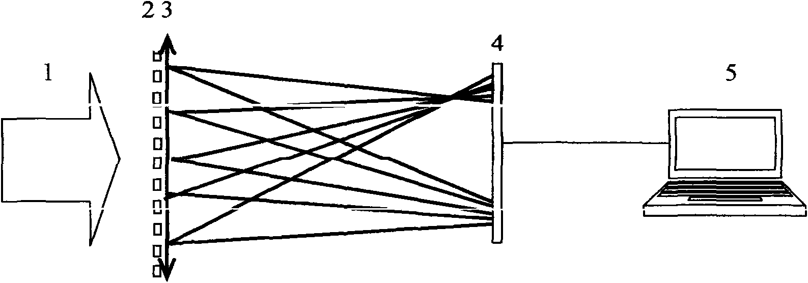
[0064] The whole detection system is composed of calibration parallel light, that is, incident laser 1, defocus grating 2, short-focus lens 3, image sensor 4 and computer 5, wherein defocus grating 2 and short-focus lens 3 are arranged in front and back, and image sensor 4 is located in this combination Afterwards, the computer 5 is located behind the image sensor 4 . The whole system works like figure 1 Shown:

[0065] Its specific working process is:

[0066] 1. The standard parallel optical calibration detection system with the same working wavelength is used, so that the image sensor is located at the focal plane of the lens, the positive and negative first-order light spots of the imaging are the same size, and the zero-order light spot is the smallest.

[0067] 2. Put the device in the optical path, and adjust the system so that the incident laser beam forms diffraction spots at various levels on the image sensor.

[0068] 4. Based on the method of image processing, ...


PUM


Abstract

The invention relates to a novel real-time detection method and a device of beam displacement drift and angle drift. The invention combines defocus grating, lenses and an image sensor, integrates angle drift detection and displacement drift detection and isolates the angle drift information and the displacement drift information of incident beams through the position changes of light spots of the image sensor. According to relative changes of positive and negative first-order light spots which form images on an imaging plane, the invention calculates the displacement drift information of the incident beams by computer programming and isolates the angle drift information of the beams according to the changes of the entire imaging light spots. The invention has the advantages of convenient operation, high measuring accuracy, wide application range and low cost, etc.

Description

technical field [0001] The invention relates to a new real-time detection method and device for beam angle drift and flat drift, which is suitable for real-time detection of laser beam drift, especially for high repetition frequency laser beam drift detection, and can be widely used in precision or ultra-precision equipment measurement, In ultrafast laser physics experiments and laser fusion. Background technique [0002] With the development of laser technology, high-precision collimated beams are playing more and more important applications in the fields of optical detection, laser ranging, and space optical communication. In small and medium-sized high repetition rate laser devices, the spatial pointing stability of the beam is very important for the research of ultrafast laser physics experiments, and the spatial pointing of the beam is required to be stable for a long time to improve the accuracy of the experiment. However, the output beam of the laser often drifts dur...

Claims


Application Information

Patent Timeline
Patent Type & Authority Applications(China)
IPC IPC(8): G01B11/26
Inventor 马浩统习锋杰刘泽金许晓军郭少锋陈金宝周朴王小林马阎星李霄汪晓波吴武明姜宗福舒柏宏
Owner NAT UNIV OF DEFENSE TECH
Why Eureka
Try Eureka