Micro electro mechanical system solid-state gyroscope with composite density and rigidity

A composite density, micro-electromechanical technology, applied in generators/motors, semiconductor/solid-state device components, piezoelectric effect/electrostrictive or magnetostrictive motors, etc., can solve the problem of limiting the vibration frequency and amplitude of the mass block. , difficult to adjust, complex structure and processing, etc., to achieve the effect of large impact resistance, simple overall structure, and improved gyro performance

Inactive Publication Date: 2011-05-04
SHANGHAI JIAOTONG UNIV
View PDF0 Cites 0 Cited by
  • Summary
  • Abstract
  • Description
  • Claims
  • Application Information

AI Technical Summary

Problems solved by technology

At present, the proof masses of most micro-inertial devices are connected to the substrate through support beams. After searching the literature of the prior art, it is found that the Journal of Semiconductors, Vol. 28, No. 10, October 2007, 1630-1635 "based on the "8 Novel x-axis tuning fork silicon micromechanical gyroscope with beam-2-mass "structure" reported a vibrating micro-gyroscope, but still did not get rid of the structural mode that the proof mass is connected to the substrate through a support beam, with 8 cantilevers There are two mass blocks in the beam, and the structure and processing are relatively complicated. This type of support structure limits the vibration frequency and amplitude of the mass block and is greatly affected by manufacturing defects and difficult to adjust, thus limiting the further improvement of the performance of the micro-inertial device. It is also difficult to improve the impact resistance of

Method used


Image

  • Micro electro mechanical system solid-state gyroscope with composite density and rigidity
  • Micro electro mechanical system solid-state gyroscope with composite density and rigidity
  • Micro electro mechanical system solid-state gyroscope with composite density and rigidity

Examples


Embodiment Construction

[0016] The embodiments of the present invention will be described in detail below. This embodiment is implemented on the premise of the technical solution of the present invention. Detailed implementation modes and specific operation procedures are given, but the protection scope of the present invention is not limited to the following implementations. example.

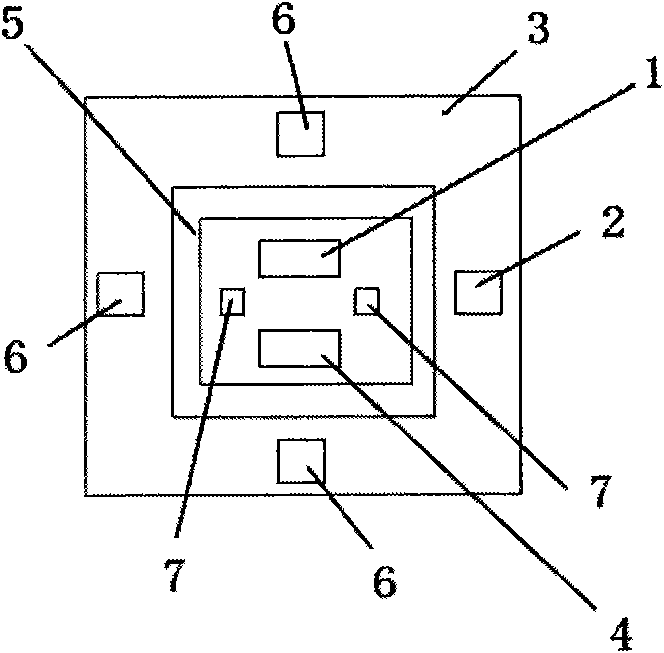
[0017] Such as figure 1 with figure 2 As shown, this embodiment includes: a vibrating drive mechanism 1, a detection mechanism 2, and a proof mass 3. The upper surface and the lower surface of the proof mass 3 are symmetrically provided with two sets of identical vibrating drive mechanisms 1 and detection masses. Institution 2.

[0018] The vibrating driving mechanism 1 includes two driving electrodes 4 symmetrically arranged on the upper surface of the proof mass 3;

[0019] The detection mechanism 2 includes: a signal interference isolation electrode 5, an angular velocity detection electrode 6 and a modal detection elec...


PUM


Abstract

A micro electro mechanical system solid-state gyroscope with composite density and rigidity in the technical field of micro electro mechanical system comprises a detection mass block, oscillation starting drive mechanisms and detection mechanisms; wherein the upper surface and the lower surface of the detection mass block are symmetrically provided with two groups of identical oscillation starting drive mechanisms and detection mechanisms respectively; the oscillation starting drive mechanisms comprise two drive electrodes symmetrically arranged on the upper surface of the detection mass block; the detection mechanisms comprises signal interference isolation electrodes, angular velocity detection electrodes and modal detection electrodes, wherein four angular velocity detection electrodesare arranged at the external edges of the lower surface of the detection mass block symmetrically in a pairwise way, two modal detection electrodes are symmetrically arranged at the middle part of the lower surface of the detection mass block, and the signal interference isolation electrodes are arranged at the outsides of the modal detection electrodes in an encirclement way. The invention dispenses with special support beam structure, the whole structure is simple, the shock resistance is great, vacuum encapsulation is unnecessary, and the gyrotropic performance can be greatly improved.

Description

Technical field [0001] The invention relates to a micro-electromechanical solid-state gyroscope in the field of micro-electromechanical technology, in particular to a micro-electromechanical solid-state gyroscope with compound density and stiffness. Background technique [0002] Microelectromechanical systems (MEMS) was formally proposed in 1989 by Professor Roger Howe, then at the University of California, Berkeley, at the Micro Wireless Robotics Conference held in Salt Lake City. In the following ten years, MEMS technology has been used in various countries around the world. The rapid development of a large amount of human and financial resources has become a very important research field. [0003] Micro-inertial sensor devices such as micro-gyros are one of the most important research fields of MEMS. At present, most of the test masses of micro-inertial devices are connected to the substrate through support beams. A literature search on the prior art found that the Chinese Jour...

Claims


Application Information

Patent Timeline
Patent Type & Authority Patents(China)
IPC IPC(8): G01C19/56B81B7/02
Inventor 张卫平陈文元吴校生崔峰刘武卢奕鹏
Owner SHANGHAI JIAOTONG UNIV
Why Eureka
Try Eureka