Microelectrode array device and special device for cell manipulation and electrophysiological signal detection

A microelectrode array, electrical signal technology, applied in measurement devices, biological tests, applications, etc., can solve problems such as distance, cell damage, and difficulty in precise alignment of neural networks and microelectrode arrays.

Active Publication Date: 2009-12-30
CAPITALBIO CORP +1
View PDF0 Cites 25 Cited by
  • Summary
  • Abstract
  • Description
  • Claims
  • Application Information

AI Technical Summary

Problems solved by technology

[0004] This kind of microelectrode array chip faces a problem: the nerve cells cultured in vitro are not accurately positioned on the electrodes, resulting in poor adhesion or distance between the cells and the electrodes, and the electrical stimulation and electrical signal detection may occur in different cells. on different parts
However, in addition to the need to effectively bind active biomolecules to the substrate, this method is difficult to achieve precise alignment between the neural network and the microelectrode array, and the modified chip cannot be reused.
[0005] In recent years, people began to try to use microelectrodes to generate dielectric force to locate nerve cells: Heida et al. Collect nerve cells through negative dielectric force; the group led by Ozkan (Prasad S. et al., J NeurosciMethods, 135(1-2): 79-88, 2004) uses 16 microelectrode array chips to directly generate posi

Method used


Image

  • Microelectrode array device and special device for cell manipulation and electrophysiological signal detection
  • Microelectrode array device and special device for cell manipulation and electrophysiological signal detection
  • Microelectrode array device and special device for cell manipulation and electrophysiological signal detection

Examples


Example Embodiment

[0042] Embodiment 1. Microelectrode array device 903 for cell manipulation and electrical signal detection

[0043] The microelectrode array device 903 for cell operation and electric signal detection of the present invention is composed of a chip unit 501 , a printed circuit board 401 and a bottomless culture cavity 506 .

[0044] 1) Prepare the chip unit 501 of the microelectrode array device

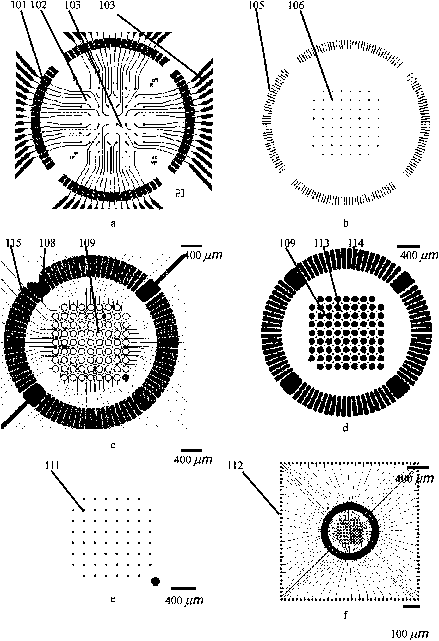
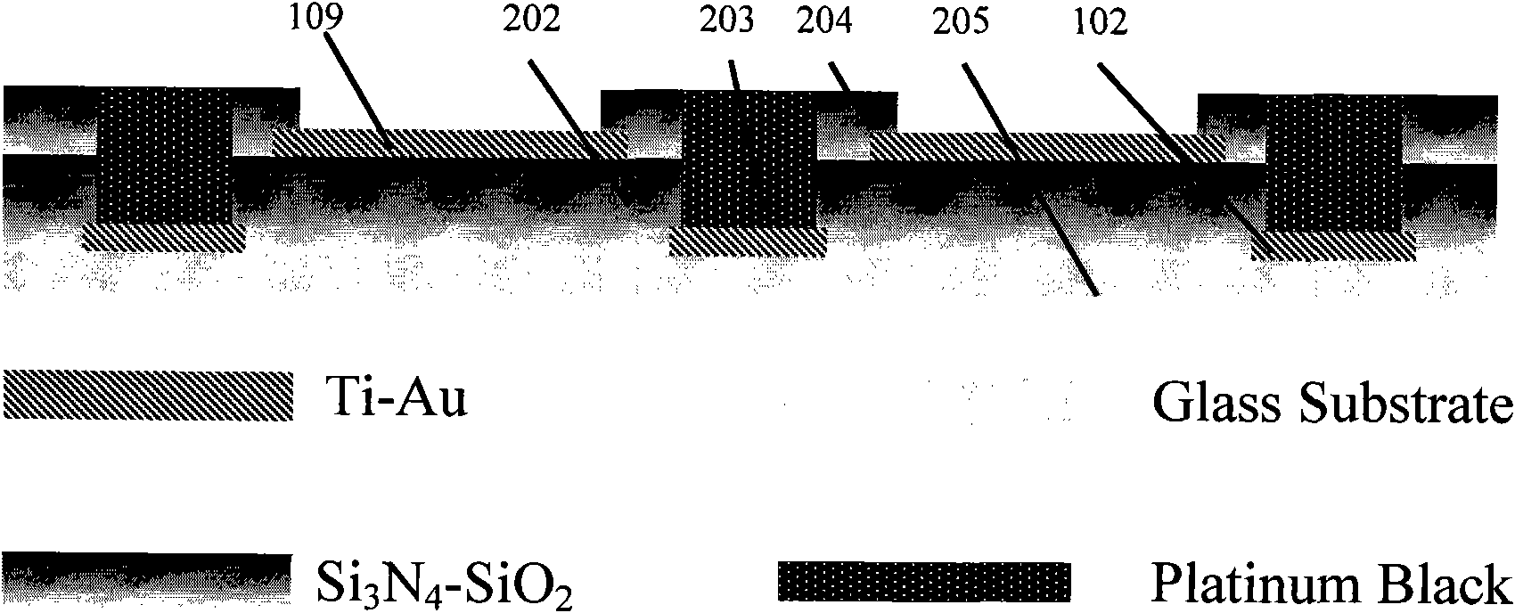
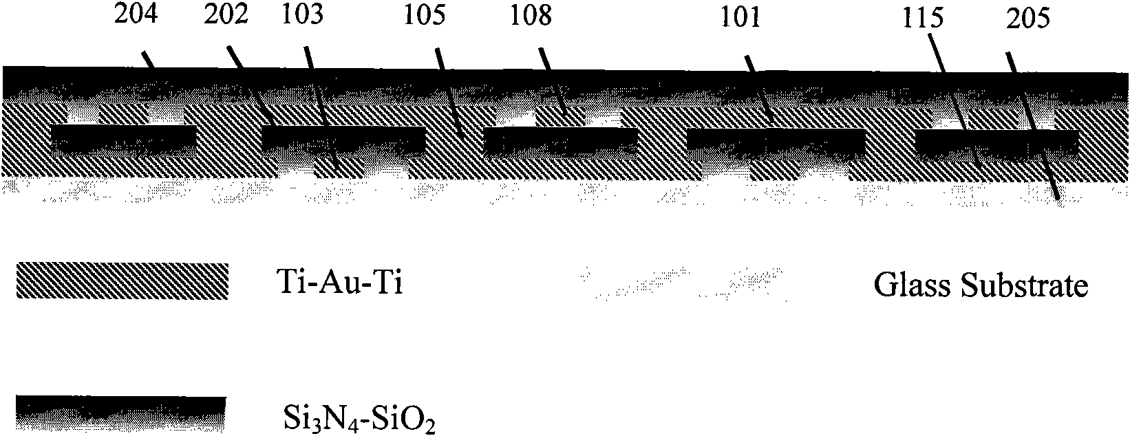
[0045] figure 1 a to e are the mask layouts for processing the chip unit 501 of the micro-electrode array device. figure 2 is a cross-sectional view of the electrode area of ​​the chip unit 501, image 3 It is a cross-sectional view of the lead area of ​​the chip unit 501. The micromachining of the chip unit is as follows:

[0046] (1) The slide 205 used is cleaned;

[0047] (2) sputtering the first metal layer, the layer structure is Ti-Au-Ti;

[0048] (3) Measuring electrodes 102, leads 103, pads 112 and ground electrodes 101 with the first mask plate a photolithography, and ...

Example Embodiment

[0068] Embodiment 2, the device that is used for cell operation

[0069] The device for cell operation of the present invention includes the microelectrode array device 903 prepared in Example 1 and a metal fixture; the preparation and assembly methods of the metal fixture are as follows:

[0070] Figure 9 It is a schematic diagram for the assembly and use of the supporting metal fixture, which consists of three parts: the metal shell 904 , the printed circuit board 905 of the metal fixture and the cover plate 901 . The printed circuit board 905 soldered with pogo pins is fixed on the hollow bottom of the metal casing 904 by four screws, the microelectrode array device 903 is placed on the pogo pins, pressed by the cover plate 901, and locked with pins 902.

[0071] Figure 10 Layout of the printed circuit board 905 for the metal fixture. Among them, 1001 is the edge of the printed circuit board, 1002 is the positioning hole and uses it to fix the printed circuit board of ...

Example Embodiment

[0075] Example 3. Application of the device for cell localization and electrical signal detection

[0076] Figure 14 It is a flowchart of localization and detection of cells by negative dielectric force. First, the cell (such as nerve cell) suspension is added to the culture cavity 506 of the device for cell positioning and electrical signal detection; then positioning signals are applied to different numbers of positioning electrodes to generate dielectric force, the difference is that both Signals can be applied to all positioning electrodes, signals can only be applied to some specific positioning electrodes, or no signal can be applied at all as a control, so that the cells can form different network patterns. The dielectric force can be generated by alternating current or direct current, and the alternating current signal can work in a wide frequency range (for example, 500Hz to 50MHz); and the positioning signal can always be applied to the positioning electrode, or it...


PUM


Abstract

The invention discloses a microelectrode array device and a special device for cell manipulation and electrophysiological signal detection. The microelectrode array device consists of a chip unit, a printed circuit board and a bottomless cultivation cavity, wherein the chip unit is arranged on the printed circuit board by pressure welding and is embedded into the cultivation cavity; the cultivation cavity is in seal connection with the printed circuit board; the chip unit comprises a substrate, a lower metal layer, an insulation layer, an upper metal layer and a passivation layer in turn frombottom to top; the lower metal layer is provided with at least one measuring electrode and a contact conductor and a bonding pad corresponding to the measuring electrode; the upper metal layer is provided with at least four positioning electrodes and contact conductors and bonding pads corresponding to the positioning electrodes; each of all measuring electrodes and positioning electrodes of the chip unit is led out by a separate contact conductor; one contact conductor is connected with one bonding pad; and each electrode can be applied with a signal or be detected independently.

Description

technical field [0001] The invention relates to a micro-electrode array device and a special device for cell operation and electrophysiological signal detection. Background technique [0002] Microelectrode array chip (microelectrode array, MEA) refers to the general term for microdevices that can detect nerve electrophysiological signals or neurotransmitters in multiple channels at the nerve cell, tissue or system level in real time. The earliest planar microelectrode array chip was created by Thomas in 1972. reported by et al., for recording the electrical activity of cardiomyocytes cultured in vitro. [0003] As mentioned above, the microelectrode array chip was first developed for the purpose of studying the characteristics and mechanism of nervous system activity. In 1949, Lilly first used the multi-tube combination microelectrode insertion method perfused with electrolyte to study the relationship between primate behavior and neuron discharge; then the microelectrode ...

Claims


Application Information

Patent Timeline
IPC IPC(8): G01N33/48A61B5/04
CPCG01N33/4836
Inventor 朱璟于中尧权雪玲项光新胡玉明邢婉丽程京
Owner CAPITALBIO CORP
Why Eureka
Try Eureka