Controller for permanent magnet synchronous motor and motor control system

A permanent magnet synchronous and control device technology, applied in the direction of motor generator control, electronic commutation motor control, motor control, etc., can solve problems such as setting errors, achieve the effects of suppressing imbalance and improving speed control accuracy

Inactive Publication Date: 2009-12-30
HITACHI LTD
View PDF1 Cites 6 Cited by
  • Summary
  • Abstract
  • Description
  • Claims
  • Application Information

AI Technical Summary

Problems solved by technology

Therefore, when position sensorless control is used, "the influence of the setting error of the resistance value in the low-speed region or the determination method" which becomes a major problem cannot be involved.

Method used


Image

  • Controller for permanent magnet synchronous motor and motor control system
  • Controller for permanent magnet synchronous motor and motor control system
  • Controller for permanent magnet synchronous motor and motor control system

Examples


no. 1 Embodiment approach

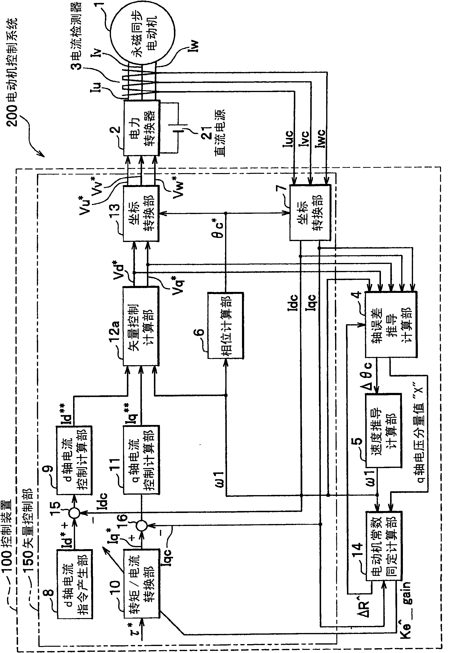
[0028] figure 1 It is an overall configuration diagram of the motor control system according to the first embodiment of the present invention.

[0029] figure 1 The motor control system 200 is composed of a permanent magnet synchronous motor 1, a power converter 2, a current detector 3, a DC power supply 21, and a control device 100. The vector control unit 150 of the control device 100 uses the torque command τ * Perform dq vector control as the target value.

[0030] The permanent magnet synchronous motor 1 is configured such that a rotor with built-in permanent magnets rotates inside a stator, and motor constants (R, Ld, Lq, Ke) define the axis of excitation (d axis) and torque axis (q axis). Voltage and current characteristics. The power converter 2 compares the voltage command value Vu * 、Vv * 、Vw * With the triangular wave, the output PWM modulates the three-phase AC voltage of the DC voltage. The current detector 3 detects the three-phase AC currents Iu, Iv, and ...

no. 2 Embodiment approach

[0182] In the first embodiment, the output value (ΔR^, Ke^_gain) of the motor constant constant calculation section 14 is used to correct the motor constant of the torque / current conversion section 10 and the shaft error derivation calculation section 4, and the output value (ΔR^ , Ke^_gain), can also be applied to the set value of the vector control calculation unit 12.

[0183] Figure 12 Each constituent element of the overall configuration diagram is changed from the vector control calculation unit 12a to the vector control calculation unit 12b. That is, except that the motor control system 210 has the control device 110, the control device 110 has the vector control unit 152, and the vector control unit 152 has the vector control calculation unit 12b, and figure 1 same.

[0184] The vector control calculation unit 12b outputs the d-axis voltage command value Vd shown in the mathematical formula (28). * and the q-axis voltage command value Vq * .

[0185] (mathematica...

no. 3 Embodiment approach

[0189] In the first embodiment, the output value (ΔR^, Ke^_gain) of the motor constant constant calculation section 14 is used to correct the motor constant of the torque / current conversion section 10 and the shaft error derivation calculation section 4, but the output value is used ΔR^ can also be applied to the calculation of the control gains of the d-axis current control calculation unit 9 and the q-axis current control calculation unit 11 .

[0190] exist Figure 13 In the overall structure diagram, except that the motor control system 220 has the control device 120, the control device 120 has the vector control unit 154, and the vector control unit 154 has the d-axis current control calculation unit 9a and the q-axis current control calculation unit 11a, the others are similar to figure 1 same.

[0191] As shown in the mathematical formula (29), if the control gain (Kp_d, Kp_q) of the d-axis current control calculation part 9a and the q-axis current control calculation ...


PUM


Abstract

The invention provides a controller for permanent magnet synchronous motor and a motor control system. Two motor constants in the two zones such as a low-speed zone and a high-speed zone are defined. A motor control system includes: a permanent magnet synchronous motor; a power converter connected to the motor, a current detector configured to detect a current flowing through the permanent magnet synchronous motor, a controller generating a control signal for controlling the power converter; the controller comprising: a vector controller configured to generate the control signal on the basis of the detected current; an axial error estimating computing unit configured to estimate an axial error information which is a difference between a phase value of the motor and the phase estimation value obtained by integrating a rotational speed estimation value of the motor; a speed estimating computing unit, which is characterized in that: a motor constant identification computing unit configured to identify a motor constant of the permanent magnet synchronous motor with the q-axis voltage component and the rotational estimation value or a rotational speed command and reflects the identified motor constant in generating the control signal by the vector controller.

Description

technical field [0001] The invention relates to a control device and a motor control system for the same fixed winding resistance value and induced voltage coefficient of a permanent magnet synchronous motor. Background technique [0002] In the sensorless vector control method of controlling a motor while omitting a position sensor, a technique of identifying motor constants is used. For example, Patent Document 1 discloses that an inverse induction voltage coefficient constanter is provided, and using the motor input voltage Vqest, the currents Idest and Iqest flowing through the motor, the rotational angular velocity ω1 of the motor, the resistance component R of the motor winding, and the d-axis inductance component Ld , the technique of performing the same calculation of the inverse voltage coefficient Φ from the calculation shown in the mathematical formula (1). The above parameters are obtained by coordinate conversion in the rotation coordinate axis of the motor, wh...

Claims


Application Information

Patent Timeline
Patent Type & Authority Applications(China)
IPC IPC(8): H02P21/14H02P25/02H02P21/00H02P21/22H02P23/14H02P27/04H02P27/06H02P29/00
CPCH02P21/146H02P21/18
Inventor 户张和明青柳滋久隅田悟士
Owner HITACHI LTD
Why Eureka
Try Eureka