Novel color brightness meter optical system

An optical system and color brightness technology, applied in the field of photoelectric integration method color brightness meter optical system, can solve the problems of complex structure and measurement speed limitation, and achieve the effect of simple and compact system structure, low power consumption and high reliability

Inactive Publication Date: 2012-01-04
ZHEJIANG UNIV
View PDF3 Cites 0 Cited by
  • Summary
  • Abstract
  • Description
  • Claims
  • Application Information

AI Technical Summary

Problems solved by technology

[0005] In the above instrument structure, in order to realize the measurement of the XYZ tristimulus value, only the red, green and blue color filter groups can be rotated by the motor inside the instrument, so that they cover the surface of the photodetector in turn, so the structure is relatively complicated. Measuring speed is limited

Method used


Image

  • Novel color brightness meter optical system
  • Novel color brightness meter optical system
  • Novel color brightness meter optical system

Examples


Embodiment Construction

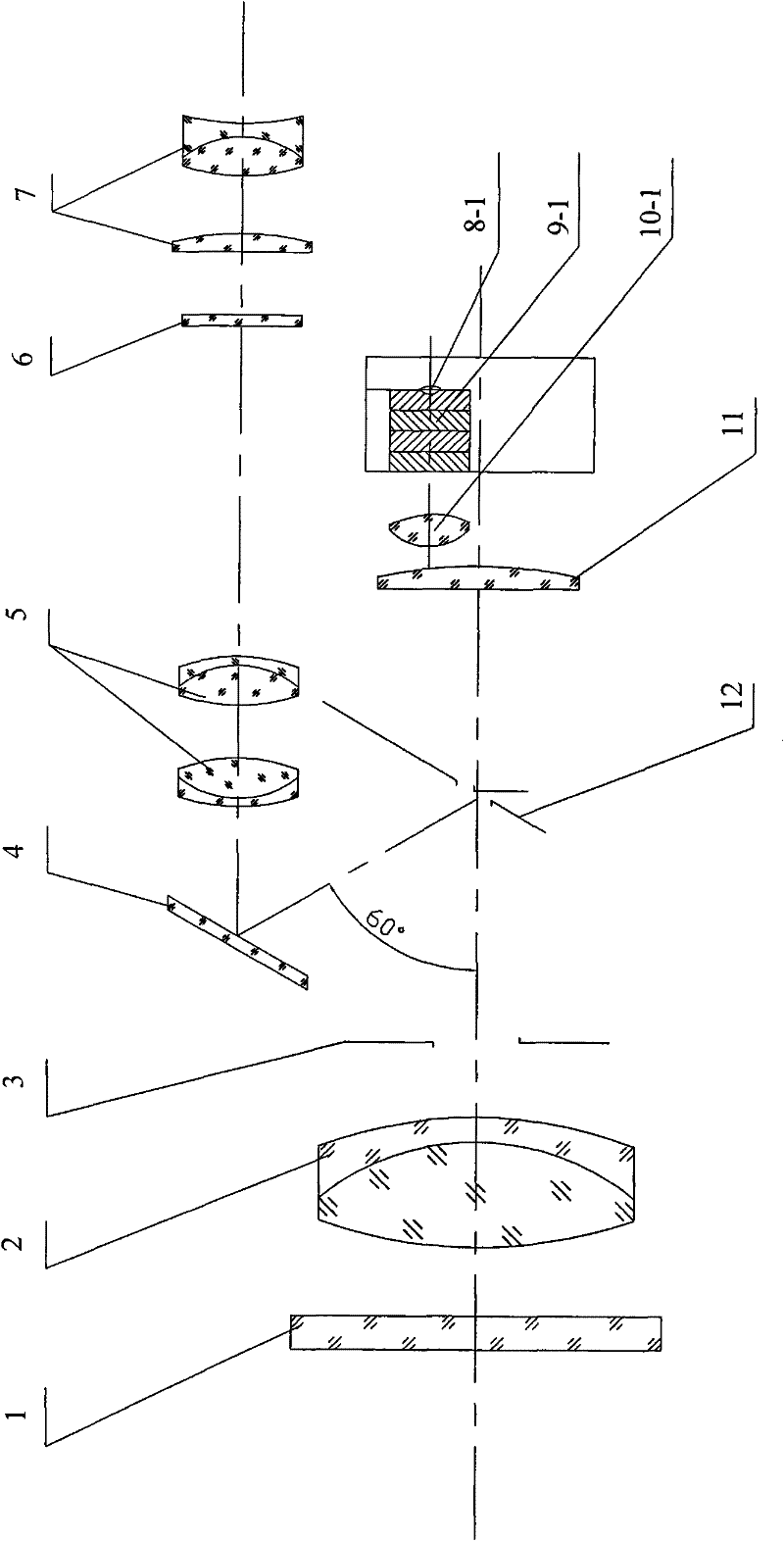
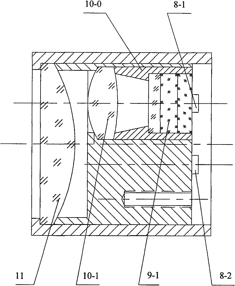
[0014] Refer to attached picture. The present invention comprises a main objective lens 2, a diaphragm 3, a perforated reflector 12, an integrating mirror 11, a reflector 4, an image transfer mirror 5, a reticle 6, and an eyepiece 7. The light beam emitted from the measured object passes through the protective glass 1, Received by the main objective lens 2, the light beam is incident on the perforated mirror 12 through the diaphragm 3 that limits the beam aperture, and the small hole on the perforated mirror 12 determines the field of view of the measuring instrument, and a part of the light beam is incident through the small hole In the integrating mirror 11, when a part of the measured target beam passes through the small hole of the perforated mirror 12, the remaining part is reflected by the perforated mirror to the mirror 4, and is imaged on the reticle 6 through the transfer mirror 5 , the observer can see the measured target clearly through the eyepiece 7 . Therefore, ...


PUM


Abstract

The invention provides a novel color brightness meter optical system which comprises a main objective, a stop, an integral mirror and a reflector with a hole. The color brightness meter optical system on an imaging light path at the back of the integral mirror is divided into three imaging areas on which three parallel light detectors are correspondingly arranged, wherein the light detectors comprise an X (Lambada) detector corresponding to a red wave band, a Y (Lambada) detector corresponding to a green wave band and a Z (Lambada) detector corresponding to a blue wave band, and a red sheet group, a green sheet group and a blue sheet group are respectively arranged in the front of the X (Lambada) detector, the Y (Lambada) detector and the Z (Lambada) detector; the color brightness meter optical system is provided with a first light path transmission structure according to the X (Lambada) detector, a second light path transmission structure corresponding to the Y (Lambada) detector anda third light path transmission structure corresponding to the Z (Lambada) detector in parallel on the imaging light path according to the three imaging areas. The novel color brightness meter optical system has the advantages of simple and compact structure, high reliability and stability and low power consumption.

Description

technical field [0001] The invention relates to an optical system of a photoelectric integration method color luminance meter. Background technique [0002] The color luminance meter is used to measure the brightness and chromaticity parameters related to color, and has been widely used in the brightness and chromaticity of color TV images, traffic lights, architectural light environments, landscape lighting, LED / LCD large-screen billboards and other related fields. checking. [0003] There are two measurement methods of color luminance meter: one is spectrophotometry, its principle is to measure the spectral composition of the target through the telescope optical system, and then according to the standard chromaticity observer spectrum three recommended by the International Commission on Illumination (CIE) Stimulus values ​​X(λ)Y(λ)Z(λ) calculate target-related luminance and chrominance parameters. This color luminance meter has high measurement accuracy, but the price is...

Claims


Application Information

Patent Timeline
Patent Type & Authority Patents(China)
IPC IPC(8): G01J1/04G01J3/46G01J3/02
Inventor 叶炜
Owner ZHEJIANG UNIV
Why Eureka
Try Eureka