Circulator

A circulator, one-cavity technology, applied in waveguide-type devices, electrical components, circuits, etc., can solve the problems of excessive size, large loss, and difficulty in widening the bandwidth, and achieve the effect of low operating frequency and low loss.

Active Publication Date: 2010-01-06
HUAYANG TECH DEV
View PDF0 Cites 7 Cited by
  • Summary
  • Abstract
  • Description
  • Claims
  • Application Information

AI Technical Summary

Problems solved by technology

However, at RF (radio frequency) or low microwave frequencies, even a double Y-junction circulator is still unacceptably large, even with high field operation
[0004] Therefore, the existing circulators that generally work below low microwave frequencies are all

Method used


Image

  • Circulator
  • Circulator
  • Circulator

Examples


Embodiment Construction

[0022] In order to describe the technical content, structural features, achieved goals and effects of the present invention in detail, the following will be described in detail in conjunction with the embodiments and accompanying drawings.

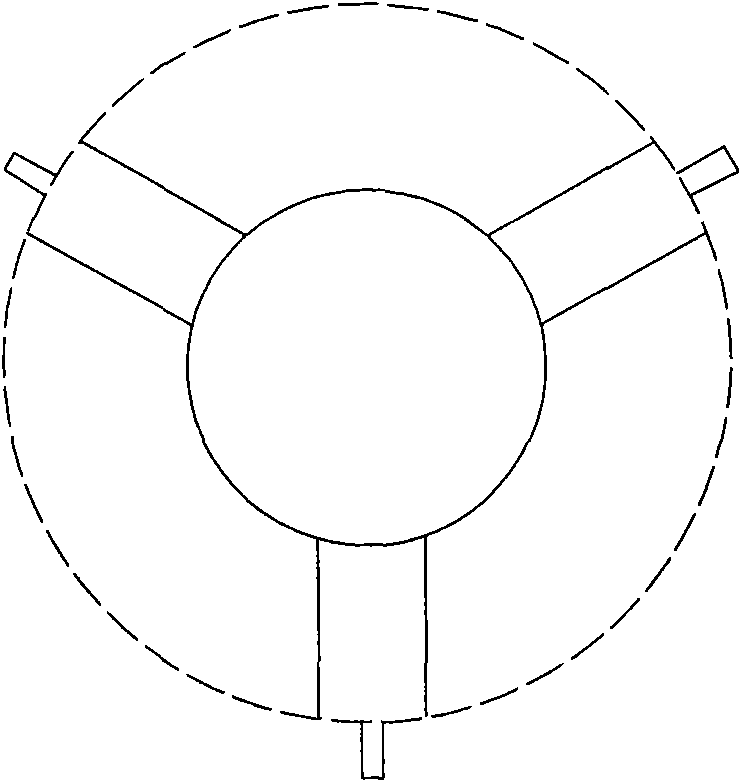
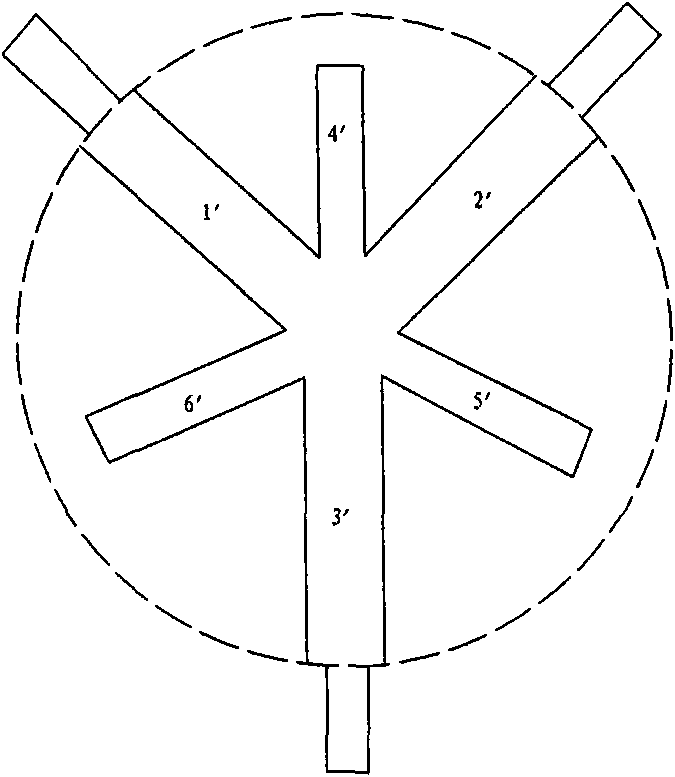
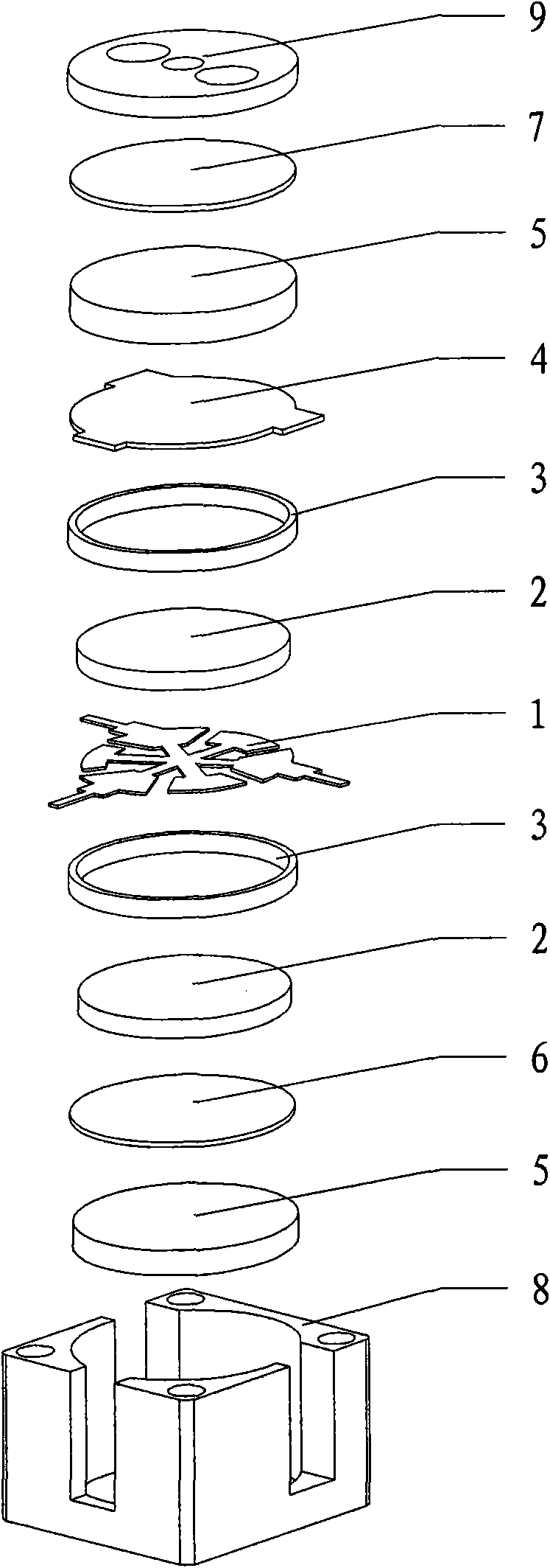
[0023] see image 3 , which is an exploded view of the structure of the circulator, which has a cavity 8, and the cavity 8 is provided with a central conductor 1, a ferrite substrate 2, a dielectric collar 3, a special-shaped silver-plated patch 4, and a permanent magnet 5. Silver-plated iron sheet 6 and compensation sheet 7. The upper and lower sides of the central conductor 1 are provided with the dielectric collar 3, the dielectric collar 3 plays a positioning role, and the dielectric collar 3 on the upper side of the central conductor 1 is provided with the The above-mentioned ferrite substrate 2, and above the dielectric collar 3 on the upper side of the central conductor 1, the special-shaped silver-plated iron sheet 4, the permanen...


PUM


Abstract

The invention discloses a circulator which comprises a cavity, wherein a center conductor and ferrite substrates are arranged in the cavity, and a cover plate is arranged at the outermost layer of the cavity; both sides of the center conductor are provided with the ferrite substrates; the center conductor is provided with a big Y branch line and a small Y branch line which are arranged at intervals; and the port of at least one of the Y branch lines is provided with a section of short capacitive transmission line, thereby being equivalent to an L/C matching network. The circulator is based ona double-Y node circulator, a section of short capacitive transmission line is extended from the port of at least one Y branch line, thereby being equivalent to the quasi-concentrated parameter L/C type matching network to replace a Y branch line forming a Y type transmission line in the prior art, thus the circulator is miniaturized. Under the same performance, the working frequency of the circulator is lower than that of the prior circulator, the loss is small, and the radius of the disk of gyromagnetic material of the circulator can be reduced to be half of that of the disk of gyromagneticmaterial of the prior conductor.

Description

technical field [0001] The invention relates to a circulator, in particular to a strip line circulator. Background technique [0002] The shape of the circulator junction formed by the center conductor determines the characteristics of the circulator. see figure 1 , which is a schematic diagram of the central conductor of the earliest disc junction circulator. According to the theory of the disc junction circulator, the disc diameter of the central conductor is proportional to the wavelength (the so-called circular condition), the lower the operating frequency, the larger the disc diameter of the central conductor. [0003] see figure 2 , which is a schematic diagram of the center conductor of the existing general double Y-junction circulator, the center conductor of the double Y-junction circulator also has this frequency dependence relationship, because it is directly evolved from the disc junction center conductor, The dual Y-junction circulator uses a dual-loop dual...

Claims


Application Information

Patent Timeline
IPC IPC(8): H01P1/383
Inventor 李海东
Owner HUAYANG TECH DEV
Why Eureka
Try Eureka