Amplitude detection and automatic gain control (AGC) circuit

An automatic gain control and amplitude detection technology, which is applied in the direction of gain control, amplification control, electrical components, etc., can solve the problems of slow reflection of AGC control circuit and output signal distortion, etc.

Inactive Publication Date: 2010-01-06
TIANJIN VAST TECH
View PDF0 Cites 26 Cited by
  • Summary
  • Abstract
  • Description
  • Claims
  • Application Information

AI Technical Summary

Problems solved by technology

However, the response of this AGC control circuit is relatively slow, generally taking hundreds of microseconds
And because the change of its common-mode voltage will affect the operating point of the subsequent stage, the post-stage amplifier works in the saturation region, resulting in distortion of the output signal

Method used


Image

  • Amplitude detection and automatic gain control (AGC) circuit
  • Amplitude detection and automatic gain control (AGC) circuit
  • Amplitude detection and automatic gain control (AGC) circuit

Examples


Embodiment Construction

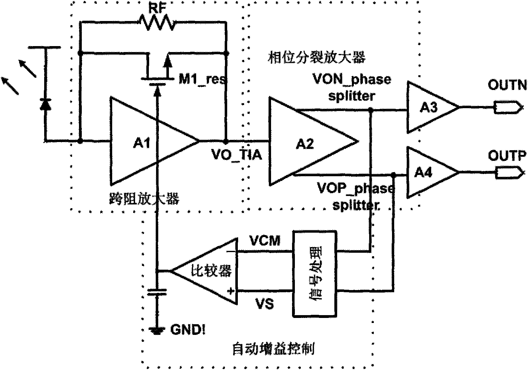
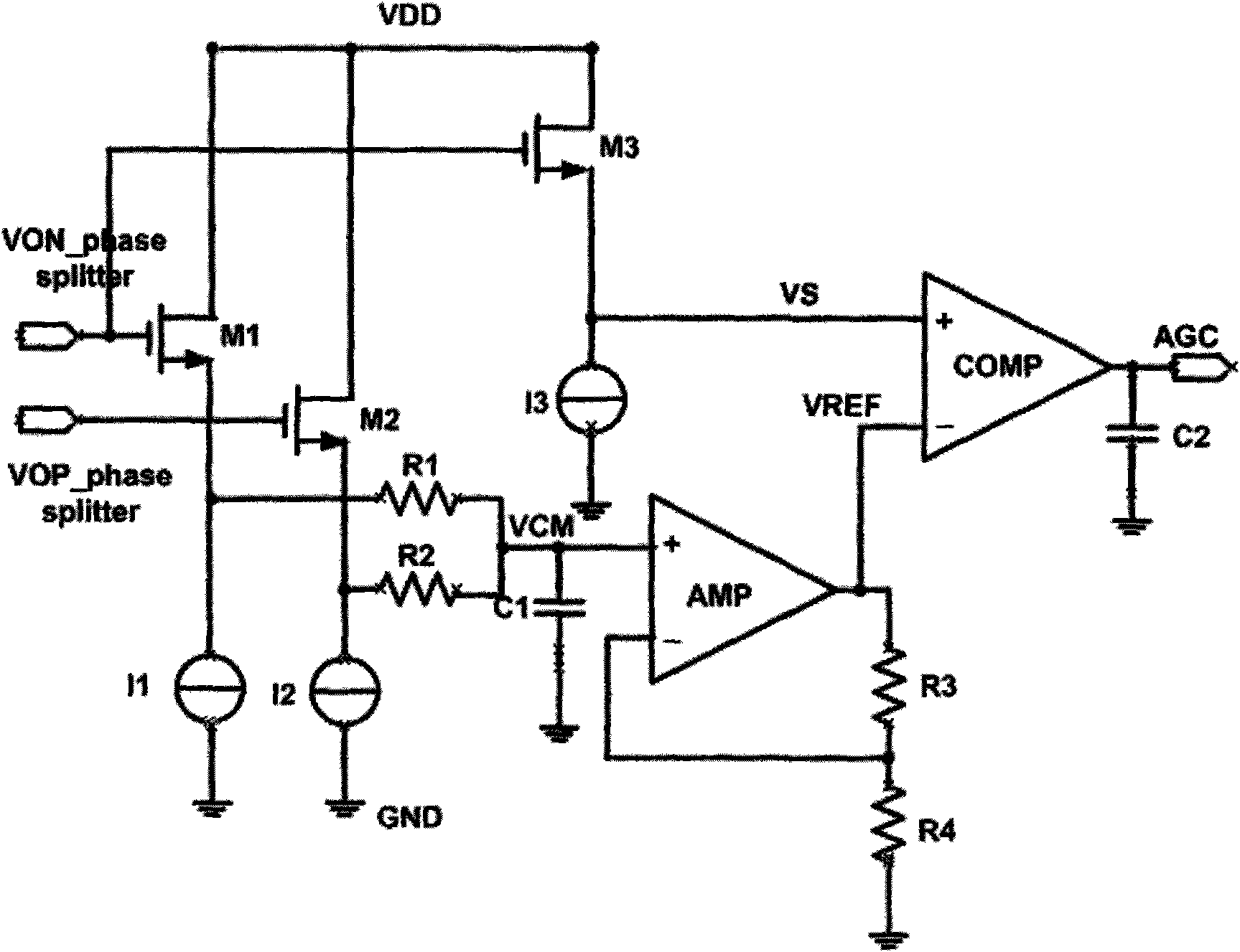
[0021] An amplitude detection automatic gain control circuit, the circuit first detects the common mode voltage of the input signal, and then inputs the common mode voltage to the negative terminal of the comparator after passing through a level shift circuit. The input signal is level-shifted by a buffer amplifier, and then input to the positive end of the comparator, and the comparison result is filtered by a capacitor to form an automatic gain control voltage.

[0022] This amplitude detection automatic gain control circuit includes the following circuits:

[0023] The input signal obtaining common mode circuit is used for obtaining the common mode voltage of the input differential signal.

[0024] The level shift circuit performs level shift on the common mode voltage of the input differential signal.

[0025] The input signal amplitude detection circuit is used to detect the amplitude of the input signal and perform level shift on the input signal.

[0026] The AGC cont...


PUM


Abstract

The invention relates to an amplitude detection and automatic gain control (AGC) circuit. An input signal is taken from a common-mod circuit and an input signal amplitude detection circuit which are respectively connected with a level-shifting circuit, and the level-shifting circuit is connected with an AGC circuit which is connected with an automatic gain circuit. The amplitude detection AGC circuit mainly has the effects that the AGC circuit can detect the amplitude of the input signal and adjusts an AGC voltage according to an amplitude value thereof to further adjust the gain of a transimpedance amplifier, and a large input signal has little output distortion.

Description

technical field [0001] The invention belongs to the field of optical fiber communication and integrated circuit design, in particular to an amplitude detection automatic gain control circuit. Background technique [0002] Fiber optic communication uses light as the information carrier and optical fiber as the transmission medium. At present, the bottleneck of the development of the optical communication industry. Microelectronic integrated circuits used in optical communication networks mainly include preamplifiers, limiting amplifiers, clock and data recovery circuits, splitters, and multiplexers. Among them, the preamplifier is directly connected with the photodetection device, and the photodetector converts the input light signal into electric current. Because the distance between the signal transmitting end and the receiving end may be very far or very close. This difference in distance is directly reflected in the strength of the optical signal. After the signals of ...

Claims


Application Information

Patent Timeline
Patent Type & Authority Applications(China)
IPC IPC(8): H03G3/20
Inventor 李景虎张勇王永生
Owner TIANJIN VAST TECH
Why Eureka
Try Eureka