Differential column-splitting inlet energy dissipater

An energy-dissipating, split-type technology, applied in water conservancy projects, marine engineering, coastline protection, etc., can solve the problems of damage to the stilling pool structure, easy cavitation damage to the middle pier, and downstream river erosion, etc. Erosion damage, avoid cavitation erosion, improve the effect of stress conditions

Inactive Publication Date: 2010-01-13
SICHUAN UNIV
View PDF1 Cites 22 Cited by
  • Summary
  • Abstract
  • Description
  • Claims
  • Application Information

AI Technical Summary

Problems solved by technology

Although the energy dissipation facility of this structure can solve the problem of relatively large water fluctuations in the stilling tank and the tail sill of the stilling tank under certain specific conditions, it has the following shortcomings: 1. The high ridge of the water inlet section (high discharge trough or discharge hole) and the outlet end of the low sill (discharge hole of the low sill) and the junction of the bottom of the stilling tank for a long time deposit mud and sand, under the action of the vertical axis vortex and horizontal axis vortex, the first bottom plate of the stilling tank is abraded , it is bound to damage the structure of the stilling pool, seriously affect the normal operation of the flood discharge facilities, and even cause major engineering accidents
2. The connection between the stilling pool and the downstream channel is not ideal, resulting in serious erosion of the downstream channel by the water flow
3. The septal pier between the high sill (high discharge trough or discharge hole) and the low sill (low sill or discharge hole) is prone to cavitation and cavitation damage

Method used


Image

  • Differential column-splitting inlet energy dissipater
  • Differential column-splitting inlet energy dissipater
  • Differential column-splitting inlet energy dissipater

Examples


Embodiment 1

[0039] The differential split-type imported energy dissipators in Embodiment 1 and Embodiment 2 are designed according to a large-scale hydropower station project with an installed capacity of 6400MW and a concrete gravity dam with a maximum dam height of 161m. The design flood (P=0.2%) flow rate of the hydropower station is 41200m 3 / s, check the flow of flood (P=0.02%) 49800m 3 / s, the maximum water level difference between upstream and downstream is 120m, and the maximum total discharge power is about 40000MW. The maximum single-width flow in the stilling pool is 225m 2 / s, the flow velocity of the stilling pool into the pool is about 40m / s.

[0040] Example 1

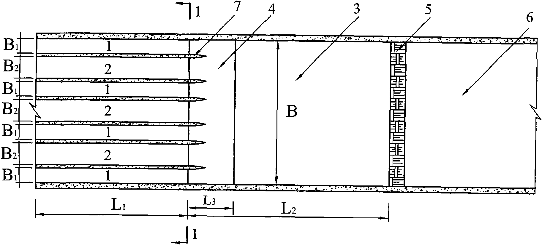
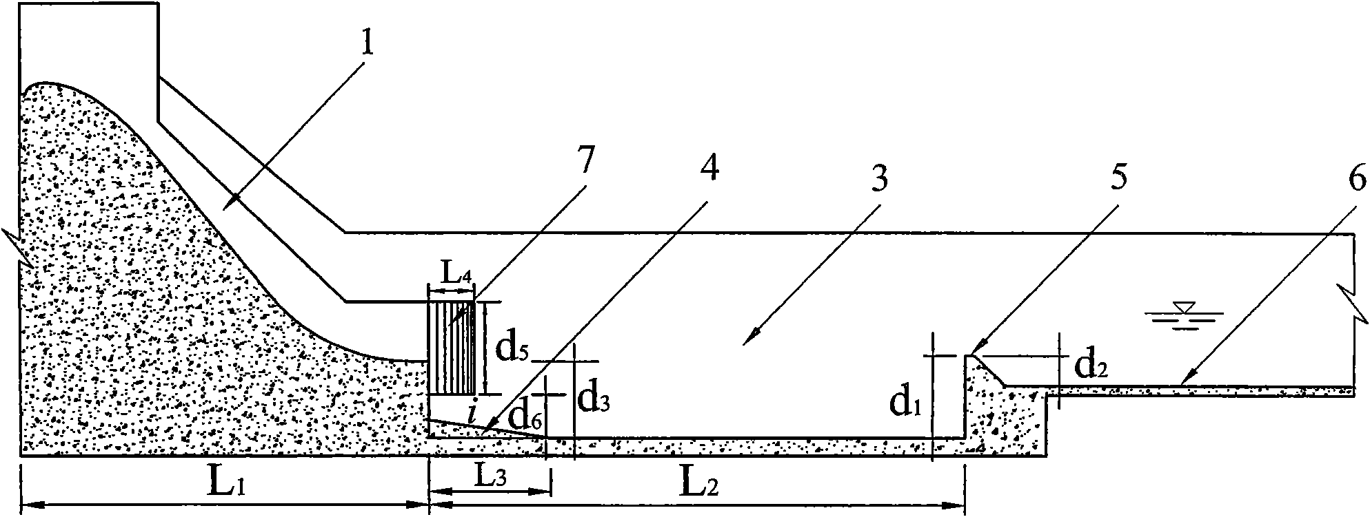
[0041] The structure of the differential split-type imported energy dissipator in this embodiment is as follows: figure 1 , image 3 , Figure 4 , Figure 7 As shown, it includes a water flow inlet section, a stilling basin 3 connected with the water flow inlet section, and an apron 6 connected with the still...

Embodiment 2

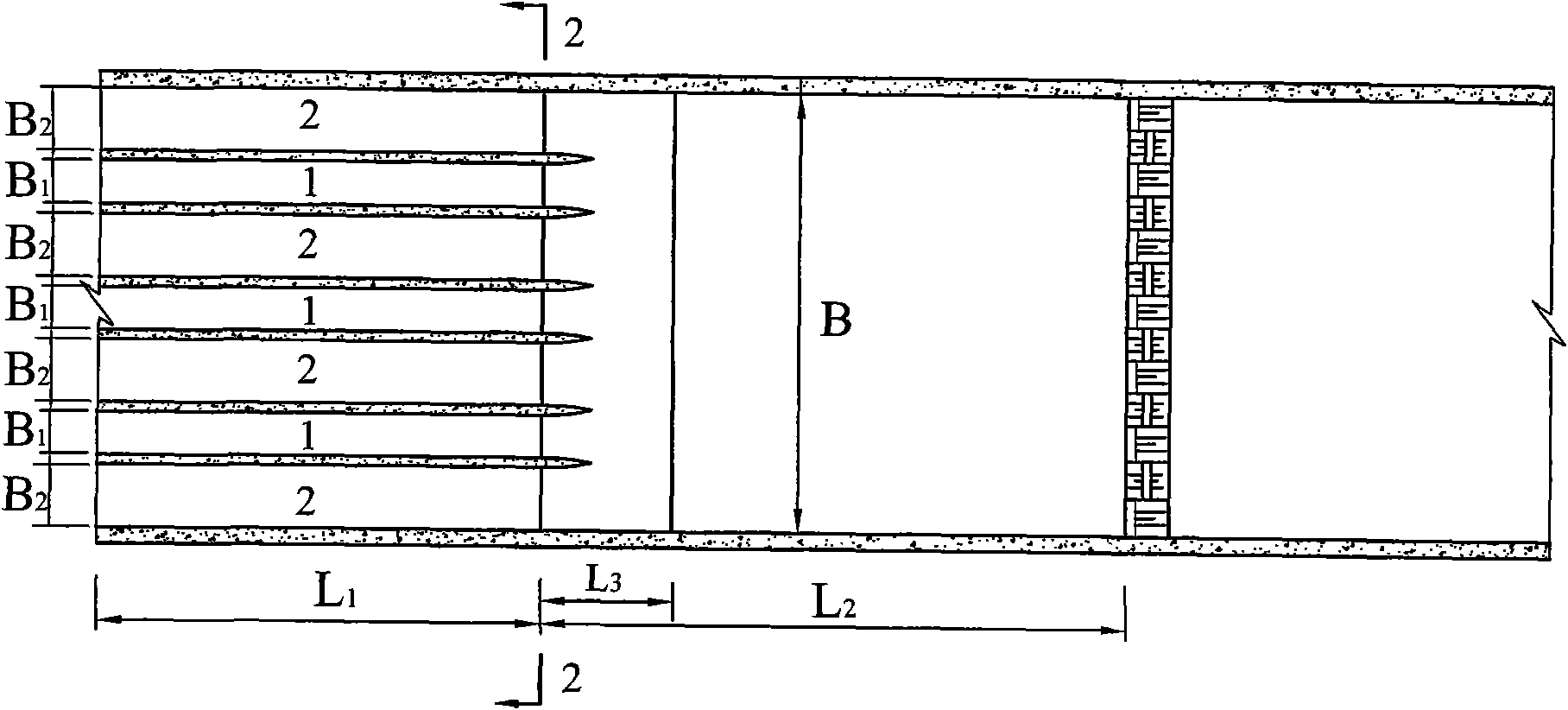
[0044] The structure of the differential split-type imported energy dissipator in this embodiment is as follows: figure 2 , image 3 , Figure 5 , Figure 10 As shown, it includes a water flow inlet section, a stilling basin 3 connected with the water flow inlet section, and an apron 6 connected with the stilling basin. The water flow inlet section is composed of high-level discharge grooves 1 and low-level discharge holes 2 arranged alternately. There are 3 high-level discharge grooves 1, 4 low-level discharge holes 2, and high-level discharge grooves 1 for non-pressure outflow, etc. Wide body type, the low discharge hole 2 is a pressure outflow, equal width body type. In the inlet section of the water flow, there is a foot 4 at the junction of the drop sill at the outlet end of the high discharge tank 1 and the outlet of the low discharge hole 2 and the bottom plate of the stilling pool. On the bottom plate of the pool, the sides perpendicular to the bottom surface in t...

Embodiment 3

[0046] The differential split imported energy dissipators in Embodiment 3 and Embodiment 4 are designed according to a large-scale hydropower station project with an installed capacity of 3000MW. The maximum dam height is 159m, and the design flood (P=0.2%) flow rate of the hydropower station is 17000m 3 / s, check the flow of flood (P=0.02%) 21000m 3 / s, the maximum water level difference between upstream and downstream is 120m, and the maximum total discharge power is about 40000MW. The maximum single-width flow in the stilling pool is 185m 2 / s, the flow velocity of the stilling pool into the pool is about 40m / s.

[0047] Example 3

[0048] The structure of the differential split-type imported energy dissipator in this embodiment is as follows: figure 2 , Figure 4 , Image 6 , Figure 12 As shown, it includes a water flow inlet section, a stilling basin 3 connected with the water flow inlet section, and an apron 6 connected with the stilling basin. The water flow i...


PUM


Abstract

The invention relates to a differential column-splitting inlet energy dissipater, comprising a water current inlet section, a stilling pool connected with the water current inlet section, and an apron connected with the stilling pool; the water current inlet section is composed of a high-level drainage channel (drainage hole) and a lower-level drainage channel (drainage hole) which are arrayed alternatively, a slim is arranged at the boundary position of a drop-sill of the outlet end part of the high-level drainage channel of the water current inlet section and the lower-level drainage channel and a bottom plate of the stilling pool, the slim is a right-angle wedge shape, the bottom surface of the right-angle wedge shape is arranged on the bottom plate of the stilling pool, and the side surface vertical to the bottom surface of the right-angle wedge shape is attached to the drop-sill of the outlet end part of the high-level drainage channel of the water current inlet section and the lower-level drainage channel, a tail sill of the stilling pool is a differential tail sill, and the top surface of the differential tail sill is formed by a combined surface unit I and a combined surface II which have different structures and are arrayed alternatively; a middle isolated pier tail between the high-level drainage channel and the lower-level drainage channel is a cantilever type streamline pier tail. The energy dissipater can improve the service life and reduces scouring damage of water current to downstream river channels.

Description

technical field [0001] The invention belongs to flood discharge and energy dissipation facilities, in particular to a water flow inlet energy dissipation facility for high water head and large unit width flow. Background technique [0002] For water flow with high water head and large unit width, its flood discharge and energy dissipation are very important, but it is also difficult, and has always been a hot and difficult issue in the research of water conservancy. The patent application with the publication number CN 101215828A discloses a high and low sill bottom flow stilling pool. Its technical solution is to adopt a suitable contraction angle on the high sill (also known as the high discharge trough) of the water inlet section, but the opposite side is high. The outer wall of the ridge does not shrink. Although the energy dissipation facility of this structure can solve the problem of relatively large water fluctuations in the stilling tank and the tail sill of the st...

Claims


Application Information

Patent Timeline
Patent Type & Authority Applications(China)
IPC IPC(8): E02B8/06
Inventor 张建民许唯临冯树荣陈伟刘善均潘江洋王韦张永涛曲景学张金婉邓军田忠陈剑刚
Owner SICHUAN UNIV
Why Eureka
Try Eureka