High-rigidity and high-precision spindle structure of spiral bevel gear grinding machine

A technology of spiral bevel gear and gear grinding machine, which is applied in the direction of belt/chain/gear, gear teeth, mechanical equipment, etc. It can solve the problems of affecting the rigidity and positioning accuracy of the grinding head, reducing the rigidity of the main shaft, and insufficient connection strength, etc., to achieve rigidity The effect of improving and improving the overall performance and stabilizing the machining accuracy

Active Publication Date: 2011-05-11
HUNAN ZDCY (ZHONGDA CHUANG YUAN) CNC EQUIP CO LTD
View PDF1 Cites 0 Cited by
  • Summary
  • Abstract
  • Description
  • Claims
  • Application Information

AI Technical Summary

Problems solved by technology

[0004] 1. The positioning connection of the secondary cone surface at the front end of the grinding head affects the rigidity and positioning accuracy of the grinding head during grinding
[0005] 2. The connection structure of the secondary cone surface of the grinding head is complicated, which leads to the long cantilever of the front spindle and reduces the rigidity of the spindle
[0006] 3. The main shaft flange is fastened on the grinding wheel main shaft by four M10 screws. Through mechanical analysis, it is found that the connection strength is not enough

Method used


Image

  • High-rigidity and high-precision spindle structure of spiral bevel gear grinding machine
  • High-rigidity and high-precision spindle structure of spiral bevel gear grinding machine
  • High-rigidity and high-precision spindle structure of spiral bevel gear grinding machine

Examples


Embodiment Construction

[0013] The present invention will be further described below in conjunction with the accompanying drawings and specific embodiments.

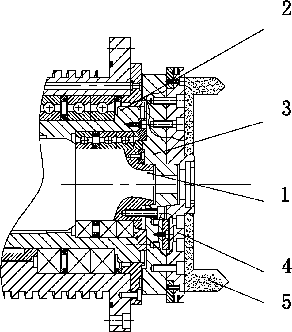
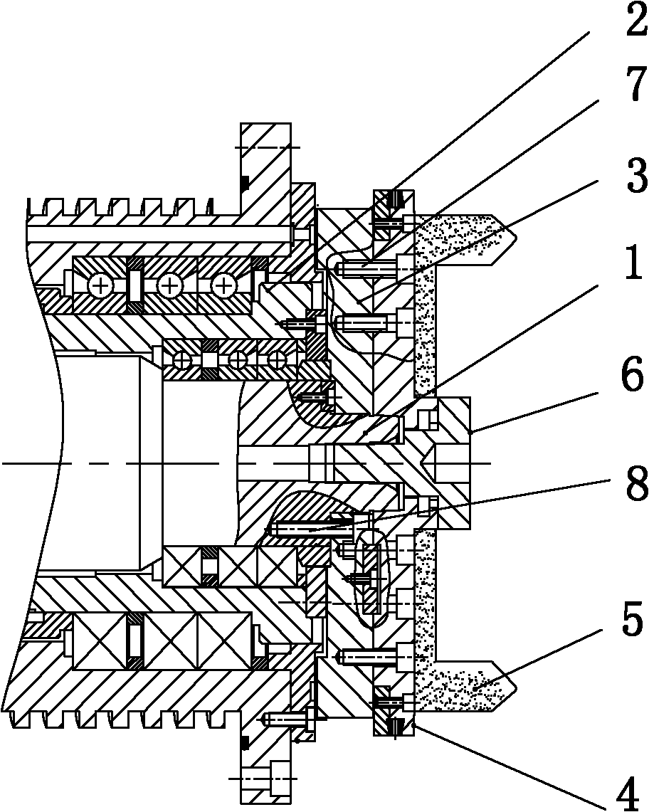
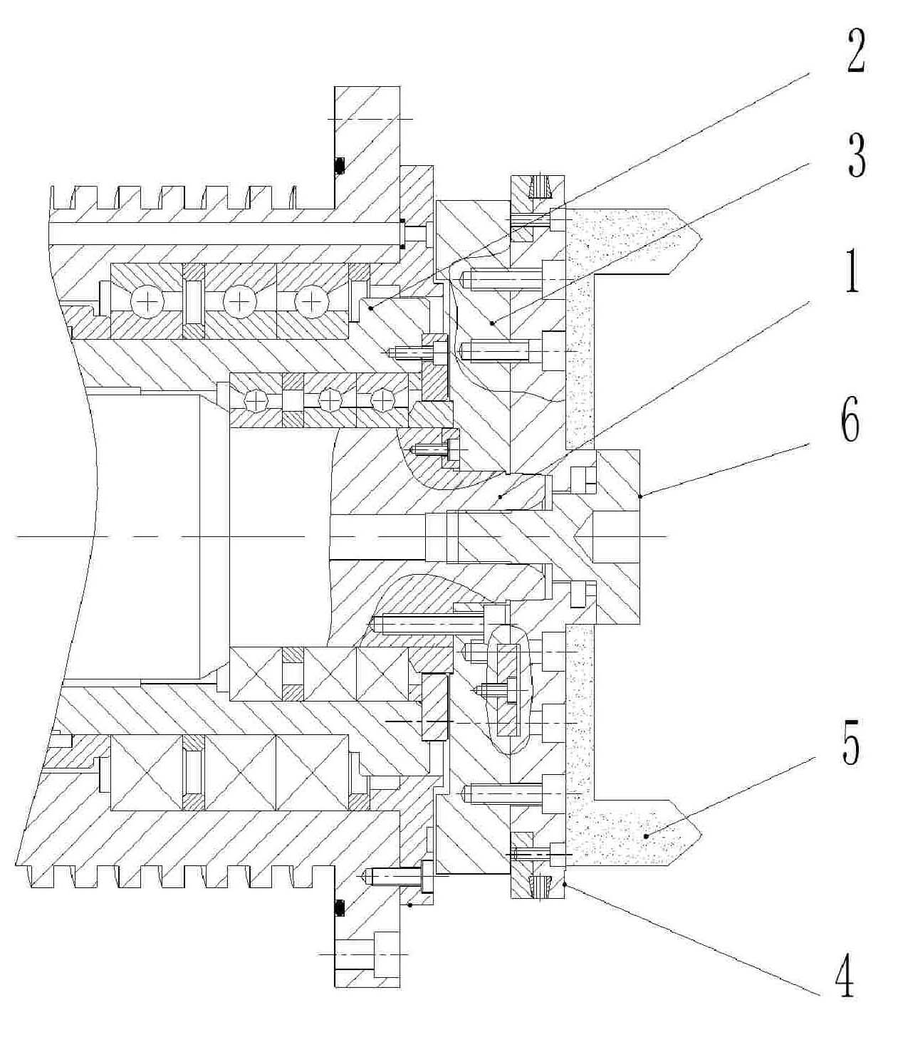
[0014] see figure 2 , the grinding wheel spindle 1 is supported on the eccentric shaft 2 by a high-precision spindle special bearing; the spindle flange 3 is positioned on the cylindrical surface of the grinding wheel spindle 1 instead of the original conical surface and is fastened on the grinding wheel spindle 1. The original 4 The fastening of one M10 screw is replaced by eight first screws 8 of M8; the grinding wheel transition plate assembly 4 is positioned through the conical surface of the grinding wheel main shaft 1 and fastened to the main shaft flange 3 by 12 second screws 7 of M8 Top: increase the fastening screw 6 to fasten the grinding wheel transition plate assembly 4 on the grinding wheel spindle 1; the grinding wheel 5 is positioned through the cylindrical surface and the end surface of the grinding wheel transition plate assem...


PUM


Abstract

The invention discloses a high-rigidity and high-precision spindle structure of a spiral bevel gear grinding machine. A spindle flange (3) is in interference fit and location with a grinding wheel spindle (1) by adopting a cylindrical surface and is fastened on the grinding wheel spindle (1) by eight M8 bolts. A grinding wheel transitional plate component (4) is interference fit and location withthe grinding wheel spindle (1) by adopting a cone surface and is fastened on the spindle flange (3). The grinding wheel transitional plate component (4) is mounted on the grinding wheel spindle (1) through a fastening screw (6) and twelve M8 bolts. The invention is the high-rigidity and high-precision spindle structure of a spiral bevel gear grinding machine with enough connection intensity and ahigh-rigidity and high-location precision grinding head when grinding, thus improving the rigidity of the grinding wheel spindle, making the machining accuracy more stable and improving the overall performance of a machine tool.

Description

technical field [0001] The invention relates to a main shaft structure of a gear grinding machine, in particular to a high rigidity and high precision main shaft structure of a spiral bevel gear grinding machine. Background technique [0002] The existing grinding head of the gear grinding machine has the phenomenon of insufficient rigidity and unstable machining accuracy during grinding after long-term use. Its structure is: the main shaft of the grinding wheel is supported by a special bearing for the high-precision main shaft and installed on the eccentric shaft, the flange of the main shaft is positioned and connected through the conical surface and fastened to the main shaft of the grinding wheel by 4 M10 screws, which is used as the front end bearing preload and the grinding wheel. The connection function of the transition plate assembly, the grinding wheel transition plate assembly is positioned through the conical surface and fastened on the spindle flange, the grind...

Claims


Application Information

Patent Timeline
Patent Type & Authority Patents(China)
IPC IPC(8): B23F9/02
Inventor 阳益江陈敢唐湘平丁志文
Owner HUNAN ZDCY (ZHONGDA CHUANG YUAN) CNC EQUIP CO LTD
Why Eureka
Try Eureka