
Method and device for removing solvent from polyethylene fiber

A polyethylene fiber and solvent technology, applied in the field of polyethylene fibers, can solve the problems of poor first solvent removal effect, large consumption of extractant, and high cost of extractant recovery, so as to save extractant, improve performance, and improve The effect of extraction efficiency

Inactive Publication Date: 2010-01-20
宁波荣溢化纤科技有限公司
View PDF0 Cites 5 Cited by
  • Summary
  • Abstract
  • Description
  • Claims
  • Application Information

AI Technical Summary

Problems solved by technology

[0009] The existing method of solvent removal is to directly extract the as-spun fibers with the extractant. The extraction process includes countercurrent, parallel flow, cross-flow and spraying, among which the cross-flow method can ensure that the fibers with solvent and The high-purity extractant is contacted, and the extraction speed is fast, but the consumption of the extractant is large, and the cost of extractant recovery is high; , the content of the first solvent in the extractant is already high, and the difference between the concentration of the first solvent in the extractant and the concentration of the first solvent in the fiber is smaller than that of cross-flow or counter-flow, so the first solvent in the polyethylene fiber The solvent removal effect is poor; in the countercurrent extraction method, because the high-purity extractant contacts the fiber that is about to leave the extraction equipment, although the first solvent content in the fiber is lower, it is still higher than the first solvent in the high-purity extractant The content of the solvent can still be removed from the fiber, so more countercurrent extraction methods are used
[0010] However, regardless of the extraction method of countercurrent, cocurrent, crossflow or spraying, the primary fiber is directly extracted. If the first solvent in the polyethylene fiber is to be removed well, the amount of extraction agent must be increased. Can remove the first solvent in polyethylene fiber very well

Method used


Image

  • Method and device for removing solvent from polyethylene fiber
  • Method and device for removing solvent from polyethylene fiber
  • Method and device for removing solvent from polyethylene fiber

Examples


Embodiment approach

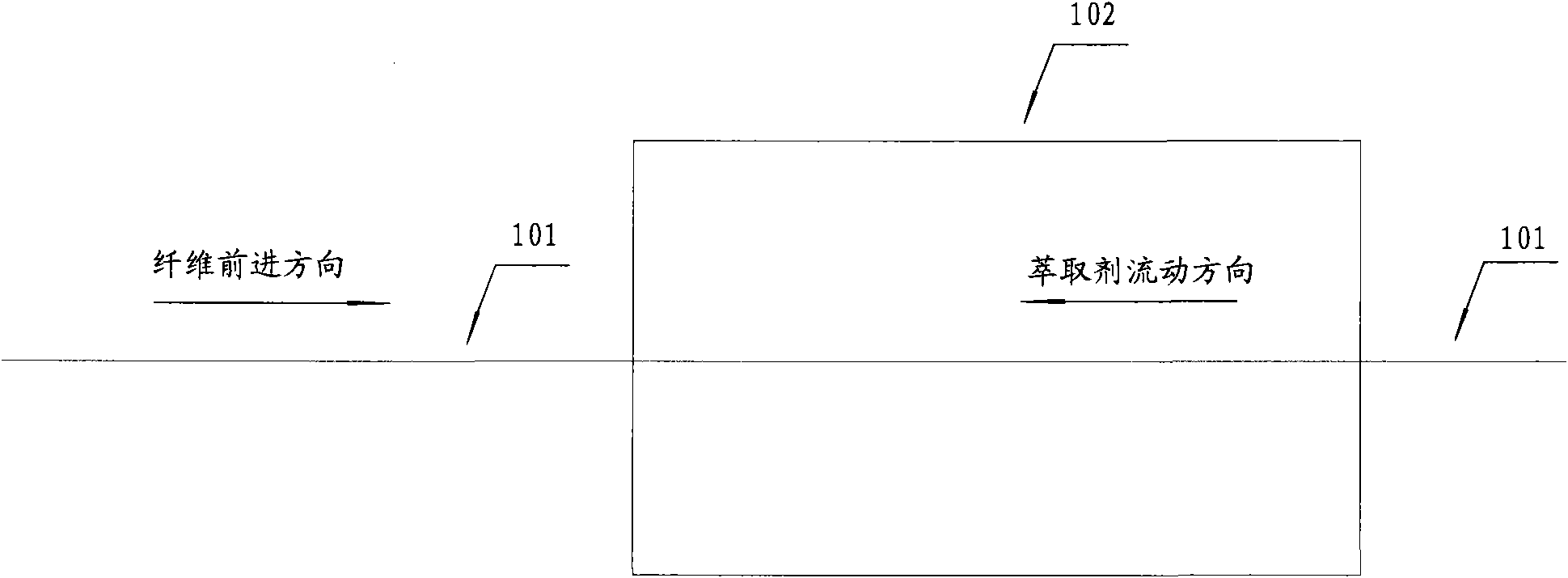
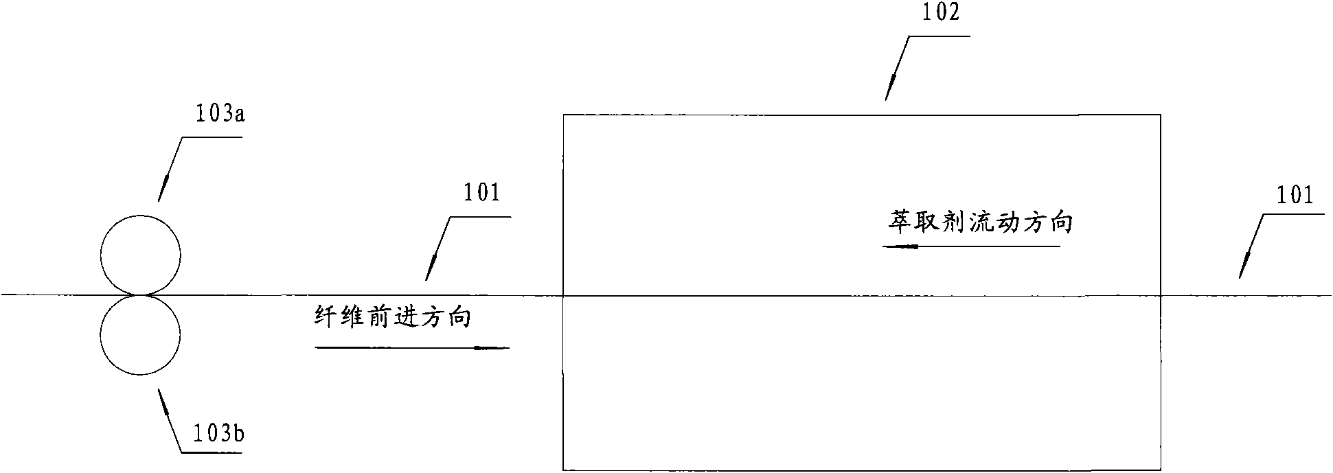
[0041] See figure 1 , figure 1 It is a schematic diagram of a method for removing solvent in polyethylene fiber in the prior art. The polyethylene fiber 101 advances in the direction shown in the figure, and the advancing direction is opposite to the flow direction of the extractant, and the polyethylene fiber 101 directly enters the extraction tank 102 without preprocessing. See figure 2 , figure 2 It is the first embodiment of the method for removing the solvent in the polyethylene fiber according to the present invention, compared to figure 1 The method for removing the solvent in the polyethylene fiber 101 shown in the prior art, in this embodiment, before the polyethylene fiber 101 enters the extraction tank 102, it first passes through a process of extruding the polyethylene fiber 101 to remove the solvent Some solvents.

[0042]In this embodiment, extruding the polyethylene fiber 101 is accomplished by a rubber roller 103a and a stainless steel roller 103b. Ther...

Embodiment 1

[0056] The polyethylene powder with a weight average molecular weight of 5 million, additives, and solvent paraffin oil are thoroughly mixed and dissolved, and then enter the twin-screw extruder. Then it enters the spinning box and is extruded into filaments through the spinneret. After cooling in the coagulation bath water tank, gel fibers are formed, and then pass through the above-mentioned rubber roller 103a and stainless steel roller 103b. The pressure between the rubber roller 103a and the stainless steel roller 103b is 15N, which is the pressure for 1000 polyethylene fibers. The extruded polyethylene fibers are extracted with solvent gasoline. The extraction equipment is an extraction tank made of stainless steel, and the extraction adopts three-stage countercurrent extraction, and the extraction temperature is 20°C. Water is added to the extraction equipment to form a water seal with a thickness of 5 cm. Then enter the drying box for drying treatment, the drying temp...

Embodiment 3

[0060] The polyethylene fibers prepared in Example 1 and Comparative Example 2 were tested for solvent content and mechanical properties respectively, and the specific data are shown in Table 1.

[0061] The performance comparison of the polyethylene fiber prepared by different embodiments of table 1

[0062] testing sample

Tensile Strength

(cN / dtex)

Tensile modulus

(cN / dtex)

Solvent content (weight

content)

Example 1

30

950

0.75%

Comparative Example 1

28

940

1.2%

[0063] From the above under the same test conditions, it can be seen that the solvent content in the final polyethylene fiber is significantly lower than that without pre-extrusion, and the mechanical properties are also improved. cN / dtex in Table 1 is the unit of specific stress, c stands for one percent, N stands for cattle, and dtex stands for dtex.

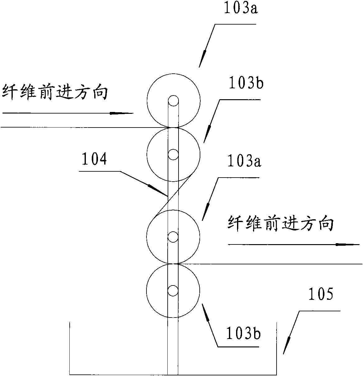
[0064] See image 3 , image 3 It is a schematic diagram of the first embodim...


PUM


Abstract

The invention discloses a method for removing a solvent from polyethylene fiber. The method comprises the following steps of: a) extruding polyethylene fiber; and b) extracting the solvent in the polyethylene fiber extruded in the step a). The invention also discloses a process for producing the polyethylene fiber by utilizing the method and the polyethylene fiber prepared by the method. The invention also discloses a device for removing the solvent in the polyethylene fiber; and the device comprises two or more rolls, wherein two rolls can be contacted under a certain pressure. Compared with the prior art, the method for removing the solvent in the polyethylene fiber, the device for removing the solvent in the polyethylene fiber and the process for producing the polyethylene fiber have the advantages of saving an extracting agent and improving extracting efficiency, and are particularly used for preparing the polyethylene fiber.

Description

Technical field [0001] The present invention relates to the production of polyethylene fibers, and in particular, to a method and device for removing solvent from polyethylene fibers, a polyethylene fiber production process using this method and polyethylene fibers prepared using this method. Background technique [0002] Ultra high molecular weight polyethylene (UHMWPE for short) fiber is also called high strength high module polyethylene (HSHMPE for short) fiber or elongation chain polyethylene (ECPE for short) polyethylene fiber or high performance polyethylene (high performance polyethylene (referred to as HPPE) fiber or high modulus polyethylene (referred to as HMPE) fiber, generally refers to the weight average molecular weight in (1 ~ 6) × 10 6 The weight average molecular weight of polyethylene fiber is sometimes higher than this value, and this fiber is simply called polyethylene fiber in the present invention. [0003] Polyethylene fiber was first developed and ma...

Claims


Application Information

Patent Timeline
IPC IPC(8): D01D10/00D01D10/06D01D13/02
Inventor 周成程
Owner 宁波荣溢化纤科技有限公司
Learn More