Modulation wave pumping rod electrical-heating oil extraction device

A technology for oil production equipment and sucker rods, which is applied to drill pipes, production fluids, earthwork drilling and production, etc., and can solve problems such as high loss, decreasing power of electrothermal conversion, and high accident rate

Inactive Publication Date: 2010-01-20
曲健
View PDF5 Cites 0 Cited by
  • Summary
  • Abstract
  • Description
  • Claims
  • Application Information

AI Technical Summary

Problems solved by technology

[0002] At present: In the process of crude oil extraction, when crude oil extraction encounters super-thick and super-high pour point crude oil, in order to achieve the purpose of being able to collect or enhance recovery, chemical methods and physical methods are often used in the process of oil recovery. Advantages and disadvantages On the basis of this technology, taking into account the outstanding effect of electrothermal oil recovery technology, various electrothermal oil recovery technologies have been widely used; with the progress and development of science and technology, the oil recovery process has been continuously updated, and in view of the characteristics of special super heavy oil development, the new vacuum insulation tube injection The integrated oil recovery technology has been recognized by the industry and has formed a scale, and it is being rapidly spread and used in the same industry around the world; due to its particularity, the electric heating oil recovery technology currently used with it is only the hollow rod intermediate frequency (the power frequency has been was eliminated) electric heating oil recovery technology, the heat tracing effect of this technology is outstanding, and it has played a vital role in the development of special super heavy oil; The high-temperature-resistant special heating cable of the same length as the hot well section must use hollow sucker rods. The reactive power loss of the intermediate frequency power supply itself is large, and the intermediate frequency current will induce heat on the outer wall of the vacuum insulation tube during operation and most of it will be lost. The frequency attenuation and frequency capacitance effect are serious. In theory, there will be a phenomenon of electrothermal conversion power decline, high failure rate, high maintenance cost, and increased load on the pumping unit; serious harmonic pollution to the power grid
For example, the patent No. ZL94230220.6 utility model patent records "hollow sucker rod over pump electric heating oil production device", the hollow sucker rod passes through the pump, and the lower end is connected to the heater under the pump. Heavy oil or high-condensation oil is heated at the same time, but due to the limitation of the principle, the heating capacity of the tip of the pump is negligible; these heating devices use industrial and medium-frequency AC power supply, and the electric energy cannot be converted into heat energy on the sucker rod to the maximum extent, which makes a large Part of the electric energy is converted into heat energy on the outer wall of the vacuum insulation tube due to electromagnetic induction and is lost. The reactive power consumption of the system is large, which is not conducive to energy saving; The internal diameter limits the cross-sectional area of ​​high-temperature cables in the well, but the electric carrying capacity cannot be increased, which limits the heating power; since the hollow sucker rod is used as the electrothermal conversion body in the circuit circuit, the cost is high, the reliability is poor, and the accident rate is high. , in principle and technical means, there are disadvantages of high loss. If the over-pump heat tracing function is enabled, a low-displacement hollow pump must be used.

Method used


Image

  • Modulation wave pumping rod electrical-heating oil extraction device
  • Modulation wave pumping rod electrical-heating oil extraction device
  • Modulation wave pumping rod electrical-heating oil extraction device

Examples


Embodiment Construction

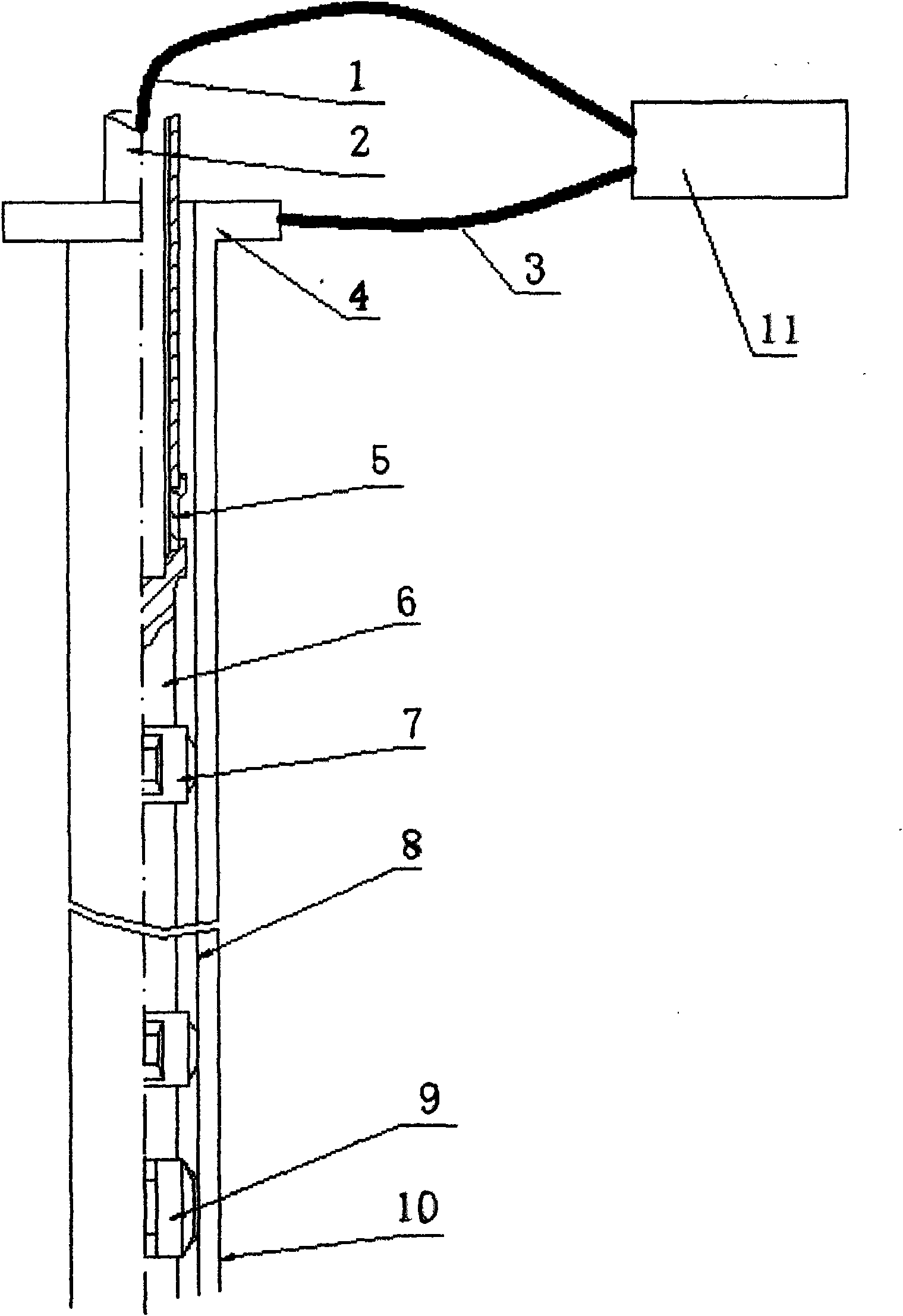
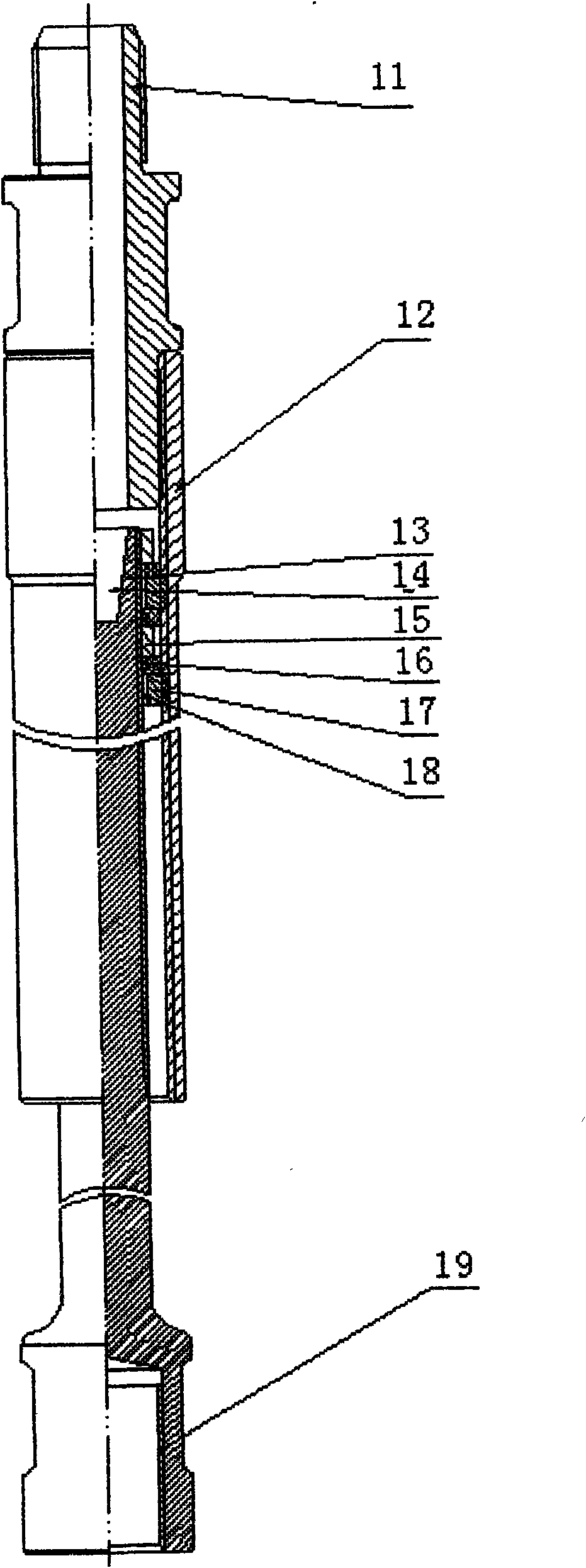
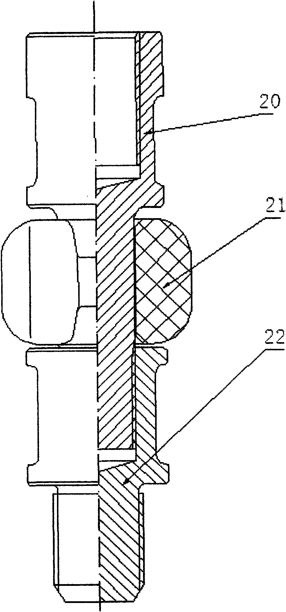
[0008] According to the accompanying drawings (such as figure 1 , figure 2 , image 3 (shown) further explains the present invention: a modulated wave sucker rod electrothermal oil production device, including 0-20Hz modulated wave power supply, hollow polished rod, hollow rod insulating pup, sucker rod, sucker rod collar insulating centralizer , incoming and outgoing cables and sliding contactors; wherein: the lower end of the hollow polished rod 2 is connected with a hollow rod insulating nipple 5, the upper and lower ends of which are in a good electrical insulation state, and the lower end of the incoming cable 1 passing through the hollow polished rod 2 is connected to the hollow The inner rod of the rod insulation nipple 5 is in good electrical connection, and the lower end of the hollow rod insulation nipple 5 is directly connected to the sucker rod 6; the sucker rod collar insulation centralizer 7 is installed at the coupling of each sucker rod 6 , used to prevent s...


PUM


Abstract

The invention relates to an oil extraction device, which is used in order to realize extraction or improve recovery when ultra-thick and ultra-high condensate crude oil occurs in the crude oil extraction process, in particular to a modulation wave pumping rod electrical-heating oil extraction device, comprising a 0 to 20Hz modulation wave power, a hollow polish rod, a hollow rod insulating short section, a sucker rod, a sucker rod coupling insulating centralizer, in/out door cables and a sliding contactor; the modulation wave pumping rod electrical-heating oil extraction device is characterized in that the lower end of the hollow polish rod is connected with the hollow rod insulating short section which consists of insulation substance infused between an outer pipe and an inner rod and staggered multi-layer inner and outer compression rings and insulation rings; the device uses the modulation wave power to supply power, has no unbalance loading and little complex pollution on grid, can transfer electrical heat on an ideal carrier, namely the sucker rod, thereby causing the crude oil to get higher and more ideal temperature rise with the same electrical energy consumption; the self reactive loss of the device is low, therefore, the device has good energy-saving effect and anti-overload ability so as to adapt to the needs of different environments.

Description

technical field [0001] The present invention relates to an oil production device used to realize collection or enhanced oil recovery when encountering super-thick and super-high-condensation crude oil in crude oil production, in particular: an electrothermal oil production device for modulated wave sucker rods. Background technique [0002] At present: In the process of crude oil extraction, when crude oil extraction encounters super-thick and super-high pour point crude oil, in order to achieve the purpose of being able to collect or enhance recovery, chemical methods and physical methods are often used in the process of oil recovery. Advantages and disadvantages On the basis of this technology, taking into account the outstanding effect of electrothermal oil recovery technology, various electrothermal oil recovery technologies have been widely used; with the progress and development of science and technology, the oil recovery process has been continuously updated, and in vi...

Claims


Application Information

Patent Timeline
Patent Type & Authority Applications(China)
IPC IPC(8): E21B43/00E21B17/10
Inventor 曲健陈帆李寅东李载敏
Owner 曲健
Why Eureka
Try Eureka