Method for identifying initial position of rotor of permanent magnet synchronous motor of non-position sensor

A permanent magnet synchronous motor, rotor initial position technology, applied in the control of generator, motor generator control, AC motor control and other directions, can solve the problems of rotor position change, complex algorithm, low identification accuracy, etc., to achieve satisfactory initial position identification The effect of precision

Inactive Publication Date: 2010-01-20
HARBIN INST OF TECH
View PDF0 Cites 88 Cited by
  • Summary
  • Abstract
  • Description
  • Claims
  • Application Information

AI Technical Summary

Problems solved by technology

[0005] The purpose of the present invention is to solve the problems of rotor position variation, low identification accuracy or complex algorithm existing in the existing methods for identifying the initial position of the rotor, and provides a method for identifying the initial position of the rotor of a permanent magnet synchronous motor without a position sensor

Method used


Image

  • Method for identifying initial position of rotor of permanent magnet synchronous motor of non-position sensor
  • Method for identifying initial position of rotor of permanent magnet synchronous motor of non-position sensor
  • Method for identifying initial position of rotor of permanent magnet synchronous motor of non-position sensor

Examples


specific Embodiment approach 1

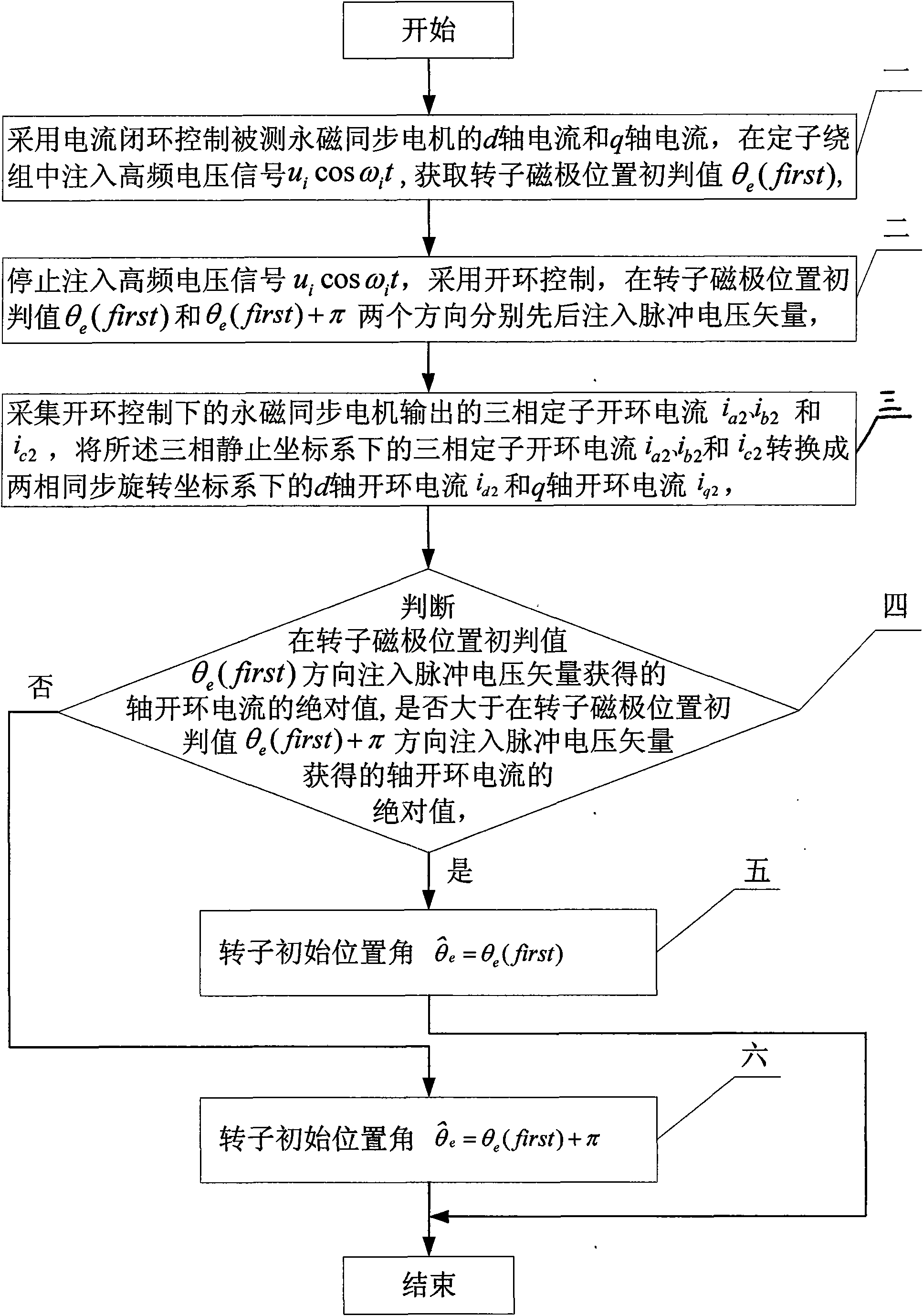
[0018] Specific implementation mode one: the following combination Figure 1 to Figure 5 Describe this embodiment, the method of this embodiment includes the following steps:

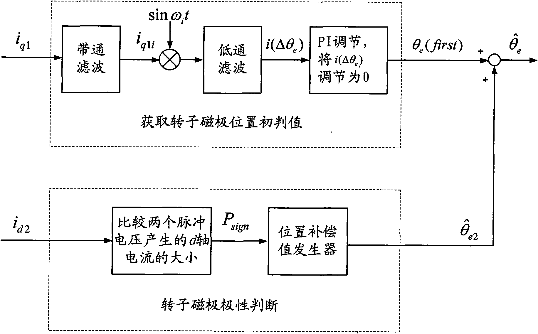
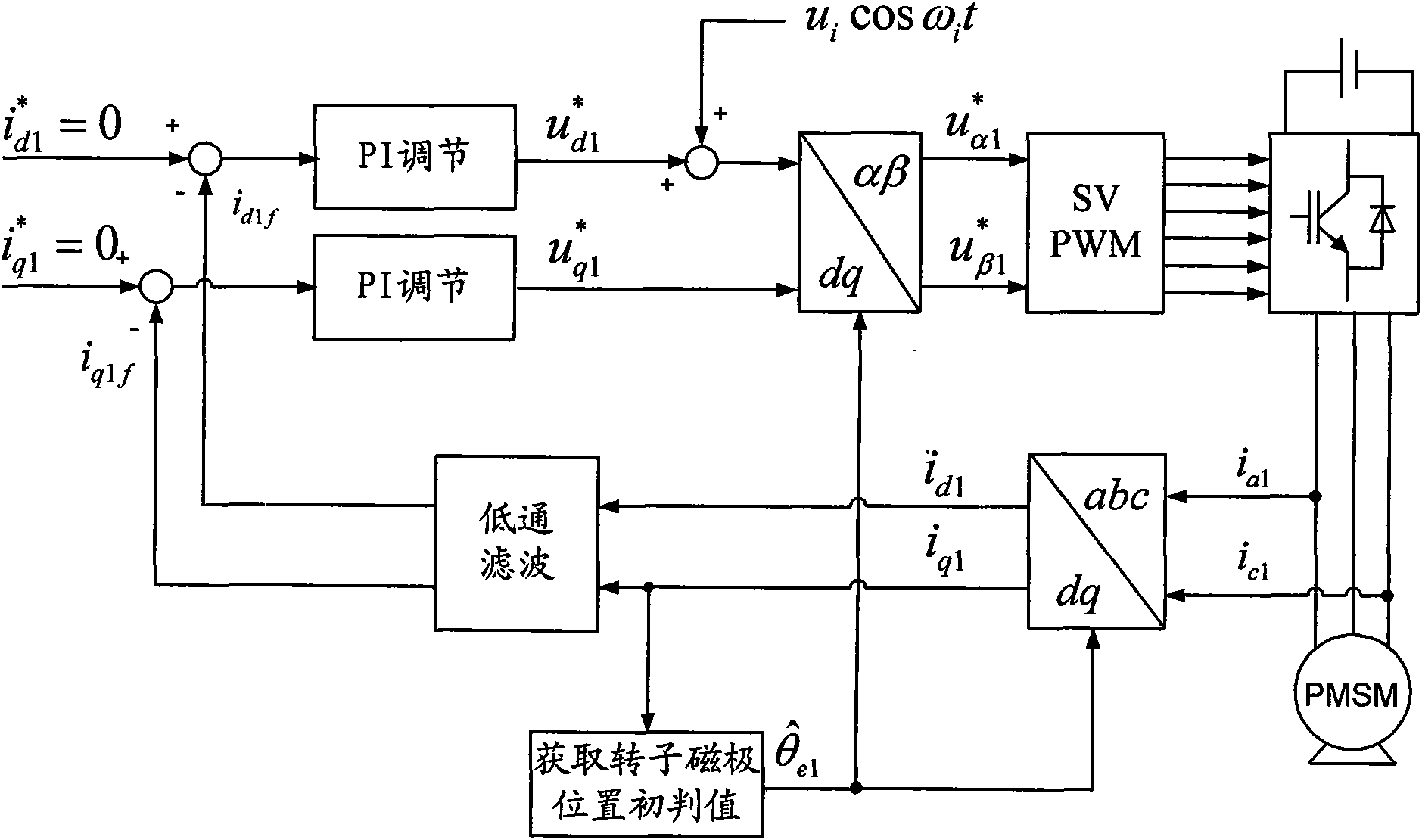
[0019] Step 1. Use current closed-loop control of the d-axis current and q-axis current of the permanent magnet synchronous motor to be tested, and inject a high-frequency voltage signal u into the stator winding i cos ω i t, to obtain the initial judgment value of the rotor pole position θ e (first), the specific method is:

[0020] Step a, initialize the following variable values:

[0021] The q-axis closed-loop given current of the permanent magnet synchronous motor stator i q 1 * = 0 , The d-axis closed-loop given current of the permanent magnet synchronous motor stator i d 1 * = ...

specific Embodiment approach 2

[0069] Embodiment 2. The difference between this embodiment and Embodiment 1 is that the high-frequency voltage signal u i cos ω i The frequency of t is 500Hz ~ 2Hz, the high-frequency voltage signal u i cos ω i Amplitude u of t i It is 15%-30% of the rated voltage of the permanent magnet synchronous motor to be tested, and the other is the same as the first embodiment.

[0070] The injected high frequency voltage signal u i cos ω i The frequency of t is much higher than the rated operating frequency of the permanent magnet synchronous motor, and the rated operating frequency of the permanent magnet synchronous motor is generally 50Hz.

specific Embodiment approach 3

[0071] Specific Embodiment 3. The difference between this embodiment and Embodiment 1 is that the high-frequency voltage signal u i cos ω i The frequency of t is 1kHz, the high frequency voltage signal u i cos ω i The frequency of t is 1kHz, the high frequency voltage signal u i cos ω i Amplitude u of t i It is 18% of the rated voltage of the measured permanent magnet synchronous motor, and the other is the same as the first embodiment.


PUM


Abstract

A method for identifying an initial position of a rotor of a permanent magnet synchronous motor of a non-position sensor belongs to the motor control field, and aims at solving the problems of the traditional method for identifying the initial position of magnetic poles of the rotor such as position change of the rotor, low identification precision or complex algorithm. The method comprises the following steps: maintaining the rotor under a static state during the identification process of the initial position of the rotor, injecting a high-frequency voltage signal to a stator winding, carrying out rotational coordinate conversion on three-phase stator current, and acquiring position information of the magnetic poles of the rotor by current components at q axis to obtain an initial judgment value of the magnetic pole position of the rotor; and then injecting two impulse voltage vectors in opposite directions to the stator winding, judging the polarity of the magnetic poles by comparing size of current components at d axis, and correcting the initial judgment value of the magnetic pole position obtained formerly by the judged polarity information of the magnetic poles to finally obtain an initial position angle of the rotor.

Description

technical field [0001] The invention relates to a method for identifying the initial position of a rotor of a permanent magnet synchronous motor without a position sensor, belonging to the field of motor control. Background technique [0002] Accurate position and speed feedback information is required in the permanent magnet synchronous motor control system. Its position detection unit is used as a feedback device, which is the guarantee of system accuracy. It provides the position information necessary for coordinate transformation for the system vector control; it provides position feedback for the position loop in the position control system. Therefore, the rotor position information plays a very important role in the permanent magnet synchronous motor control system. [0003] Due to the advantages of high power density and high efficiency, permanent magnet synchronous motors have been widely used in many industrial control occasions. In practical applications of perm...

Claims


Application Information

Patent Timeline
Patent Type & Authority Applications(China)
IPC IPC(8): H02P21/00H02P6/18H02P21/18H02P21/32H02P25/022
Inventor 王高林杨荣峰于泳陈伟徐殿国
Owner HARBIN INST OF TECH
Why Eureka
Try Eureka