Supercharge Your Innovation With Domain-Expert AI Agents!

Discharge lamp lighting device and projector

A technology for lighting devices and discharge lamps, applied in the field of projectors, can solve problems such as electrode damage of discharge lamps, and achieve the effects of reducing power consumption, sacrificing response speed, and fast response speed

Inactive Publication Date: 2010-01-27
SHARP KK
View PDF4 Cites 0 Cited by
  • Summary
  • Abstract
  • Description
  • Claims
  • Application Information

AI Technical Summary

Problems solved by technology

In this case, a rush current of a large current flows through the discharge lamp at the moment when the insulation is broken, causing a problem that the electrodes of the discharge lamp are damaged.

Method used


Image

  • Discharge lamp lighting device and projector
  • Discharge lamp lighting device and projector
  • Discharge lamp lighting device and projector

Examples


Embodiment approach 1

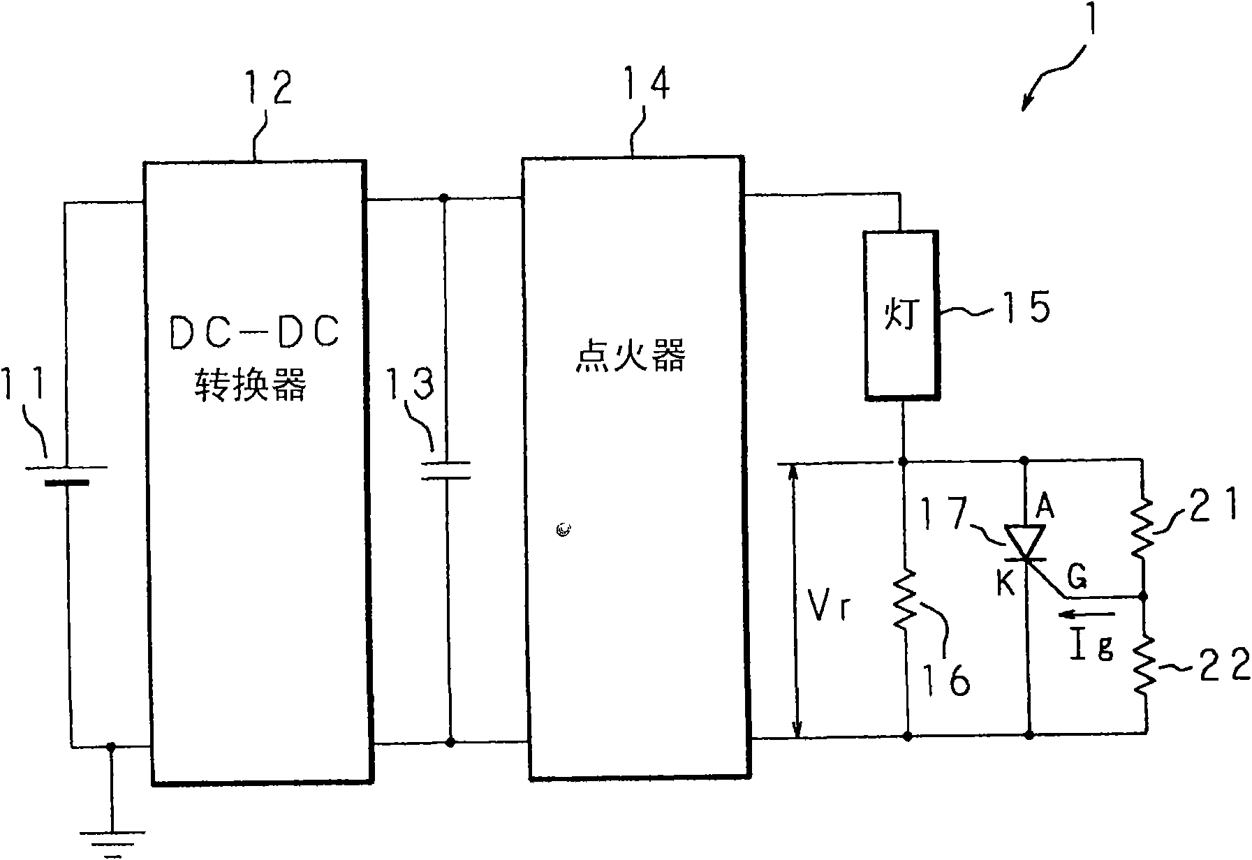
Embodiments of the present invention will be described below with reference to the drawings. figure 1 It is a circuit diagram showing the circuit configuration of the discharge lamp lighting device 1 . In the figure, 1 is a discharge lamp lighting device (hereinafter referred to as lighting device 1), including: DC power supply 11, DC-DC converter 12, capacitor 13, igniter 14, discharge lamp (hereinafter referred to as lamp) 15 , Resistor 16, SCR 17, auxiliary resistor 21 and protection resistor 22. The DC-DC converter 12 is connected to the DC power supply 11 . The capacitor 13 is connected in parallel in the subsequent stage, and the igniter 14 is also connected in the subsequent stage. The DC-DC converter 12 boosts or steps down the voltage from the DC power supply 11, and makes the power supplied to the lamp 15 the rated value of the lamp 15 by turning on / off an internal switching element not shown in the figure. Light control. The capacitor 13 is used to smooth and red...

Embodiment approach 2

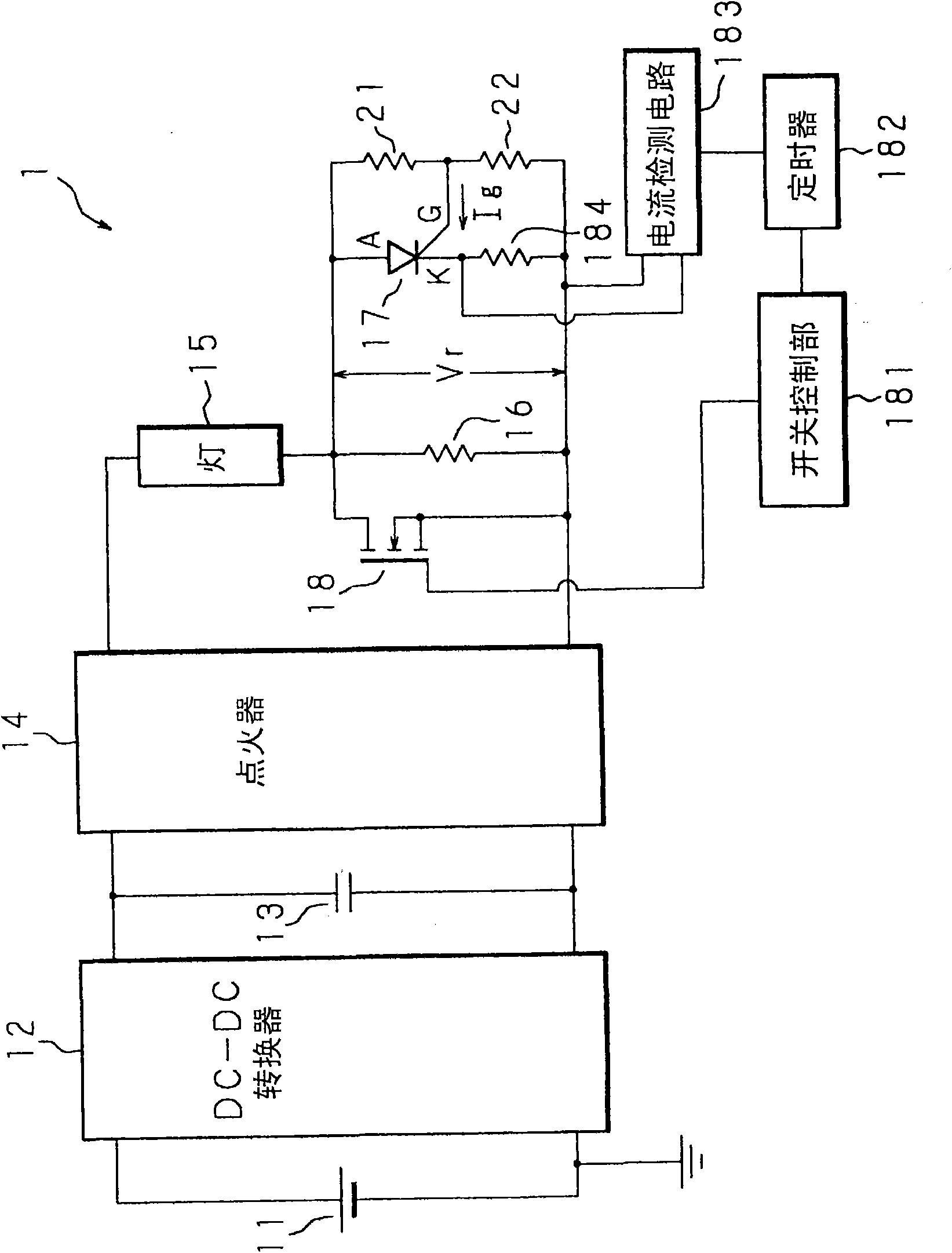
Embodiment 2 relates to a method of further reducing power consumption by separately connecting switching elements in parallel and turning on the switching elements after a predetermined time elapses. image 3 It is a circuit diagram of the circuit configuration of the lighting device 1 according to the second embodiment. In addition to the configuration of Embodiment 1, the configuration further includes a switching element 18 , a switching control unit 181 , a timer 182 , a current detection circuit 183 , and a current detection resistor 184 . For the switching element 18, for example, a FET (hereinafter referred to as FET 18 ) is used. The FET 18 is connected in parallel to the resistor 16 , the thyristor 17 , and the auxiliary resistor 21 and the protection resistor 22 .

[0038] The drain of the FET 18 is connected to the lamp 15 , the source is connected between the igniter 14 and the resistor 16 , and the gate is connected to the switching control unit 181 . The switch...

Embodiment approach 3

A projector to which the lighting device 1 described above is applied. Figure 4 It is a block diagram showing the hardware configuration of the projector. The structure of the projector 30 includes: the lighting device 1 of Embodiment 1 or 2, the lamp 15, the reflector 321, the color wheel 32, an image forming device (hereinafter referred to as DMD (Digital Micromirror Device (registered trademark))) 36, an image forming Element control circuit 37 , projection lens 38 , fan 33 , main control section 39 , and image signal processing section 391 .

[0043] The main control unit 39 controls each part of the above-mentioned hardware according to a program stored in a memory not shown. The image signal is input to the image signal processing unit 391 . The image signal processing unit 391 performs image signal processing such as synchronization separation and scaling, and outputs the processed image signal to the image forming element control circuit 37 . In the projector 30 , t...


PUM


Abstract

There are provided a discharge lamp lighting device, capable of reducing rush current and power consumption and having a high response speed, and a projector equipped with the discharge lamp lighting device. A resistor (16) is connected to a lamp (15) in series. A thyristor (17) and an auxiliary resistor (21), one end of which is connected to the gate of the thyristor (17), are connected with the resistor (16) in parallel. The resistance value of the internal equivalent resistance when the thyrister (17) is in an on-state is smaller than the resistance value of the resistor (16). The resistor (16) eliminates a rush current flowing when the lamp (15) is lighted. After that, a current flows between the anode and the cathode of the thyristor (17).

Description

technical field [0001] The present invention relates to a discharge lamp lighting device for lighting a discharge lamp, and more particularly to a discharge lamp lighting device that reduces a rush current when starting to light a discharge lamp, and a device having the discharge lamp lighting device. projector. Background technique [0002] A short-arc metal halide lamp or a high-pressure mercury lamp is used in a liquid crystal projector, an overhead projector, or general lighting, and a discharge lamp lighting device is used to light the metal halide lamp. A discharge lamp lighting device used in a projector or the like generates a high voltage of several tens of kV through an igniter at the time of start-up, and causes insulation breakdown by applying it to the discharge lamp. In this case, a rush current of a large current flows through the discharge lamp at the moment of insulation breakdown, causing a problem that the electrodes of the discharge lamp are damaged. Th...

Claims


Application Information

Patent Timeline
Patent Type & Authority Applications(China)
IPC IPC(8): H05B41/282
CPCH05B41/2923H05B41/2886Y02B20/202Y02B20/00
Inventor 伊藤宽
Owner SHARP KK
Features
  • R&D
  • Intellectual Property
  • Life Sciences
  • Materials
  • Tech Scout
  • Unparalleled Data Quality
  • Higher Quality Content
  • 60% Fewer Hallucinations
Learn More