Reduction method of lead-rich slag

A technology of enriching lead slag and reducing agent, which is applied in the field of metal smelting to reduce costs and pollution and ensure safety

Inactive Publication Date: 2010-02-10
岷山环能高科股份公司
View PDF0 Cites 6 Cited by
  • Summary
  • Abstract
  • Description
  • Claims
  • Application Information

AI Technical Summary

Problems solved by technology

A flue gas treatment system is installed after the slag is directly reduced to fine coal and the furnace body

Method used


Image

  • Reduction method of lead-rich slag
  • Reduction method of lead-rich slag

Examples


Embodiment Construction

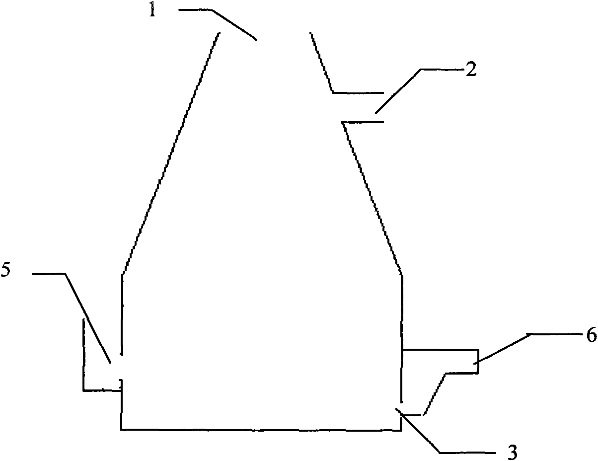
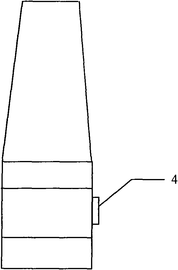
[0008] as attached figure 1 The lead-rich slag shown in the figure enters the furnace through the slag inlet 5, and the powdered coal or coke particles are added from the furnace upper port 1. The side blowing device 4 is used to blow in coalbed methane or natural gas to provide supplementary heat, and the oxygen-enriched air is assisted to raise the temperature of the slag. Above 1100°C, use nitrogen to stir the melt to make the upper reducing agent fully react with the slag, and use the exothermic heat of the reduction reaction to stabilize the temperature of the reaction melt region at 1200-1250°C, which can effectively promote the smooth progress of the reaction. The mixed siphon method of slag and lead is adopted to put it into the front bed 6 from the siphon outlet 3, and the lead and slag are separated in the front bed 6 after static clarification. In order to make full use of the heat of the flue gas and ensure the safety of the flue gas system, the 2. After that, a su...


PUM


Abstract

The invention provides a reduction method of lead-rich slag, which belongs to the field of metallurgy and comprises the following steps: adding liquid-state lead-rich slag into a furnace from a slag inlet, adding slack coal or pulverized coke particles used as a reducer into the furnace from an upper port of the furnace, stirring the fusant by using nitrogen so that the reducer and the slag are completely mixed, blowing coal bed gas or natural gas by using a side blower to assist oxygen-rich air to increase the slag temperature to above 1100 DEG C, and simultaneously keeping the temperature ofthe fusant area at 1200-1250 DEG C by utilizing the reaction heat. The method does not use coke so as to effectively reduce the cost and the environmental pollution.

Description

a technical field [0001] The invention relates to a method for reducing lead-rich slag, which belongs to the field of metal smelting. Two background technology [0002] my country is the country with the largest lead production and consumption in the world, and the technical level of lead smelting has also been continuously improved with the substantial increase in output. Oxygen top blowing technology, oxygen bottom blowing technology, Kaldor furnace and oxygen side blowing technology, these technologies The technology of sintering lead smelting has been eliminated, the heat utilization efficiency and sulfur utilization rate of materials have been improved, and energy consumption has been reduced. The technology simultaneously produces lead-rich slag. Lead-rich slag must be further processed in the lead smelting process. This part of the material contains about 45% to 60% of the total input material. At present, the commonly used treatment technology for lead-rich slag in m...

Claims


Application Information

Patent Timeline
Patent Type & Authority Applications(China)
IPC IPC(8): C22B7/04C22B13/02
CPCY02P10/20
Inventor 何秋安何志军孙富有何志刚何国才易超许素敏
Owner 岷山环能高科股份公司
Why Eureka
Try Eureka