Biomass furnace combustor and combustion method thereof

A biomass and burner technology, which is applied in the direction of combustion methods, use of multiple fuels, combustion types, etc., can solve the problems of insufficient secondary gasification combustion, etc., to save fuel costs, increase combustion efficiency, and improve heat energy The effect of conversion rate

Inactive Publication Date: 2011-04-20
宁波双翼能源科技有限公司
View PDF1 Cites 0 Cited by
  • Summary
  • Abstract
  • Description
  • Claims
  • Application Information

AI Technical Summary

Problems solved by technology

[0004] The main purpose of the present invention is to provide an industrial biomass semi-gas furnace installed in the prior art for the technical problem of insufficient secondary gasification and combustion of industrial coal or biomass semi-gasification hot air stove or water heater. Above, a biomass stove burner that can eliminate smoke and improve the conversion rate of fuel heat energy

Method used


Image

  • Biomass furnace combustor and combustion method thereof
  • Biomass furnace combustor and combustion method thereof
  • Biomass furnace combustor and combustion method thereof

Examples


Embodiment 1

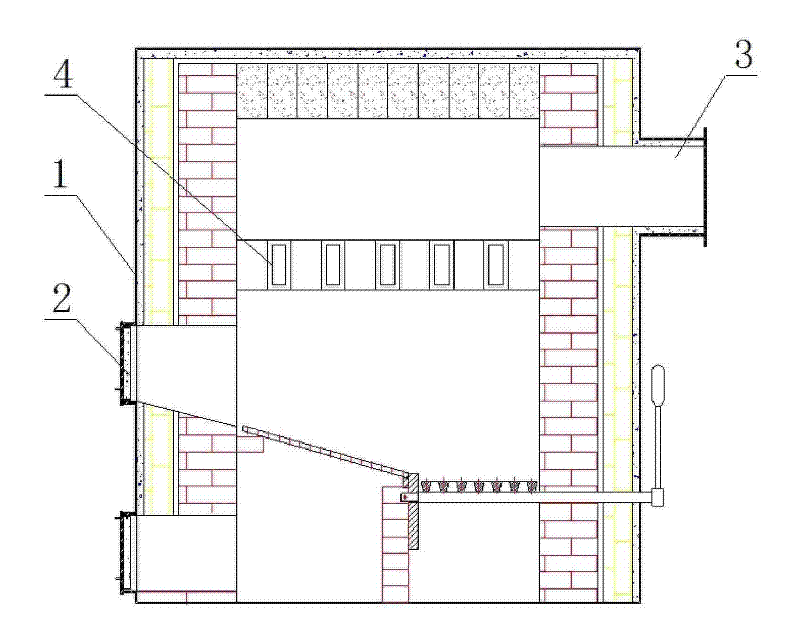
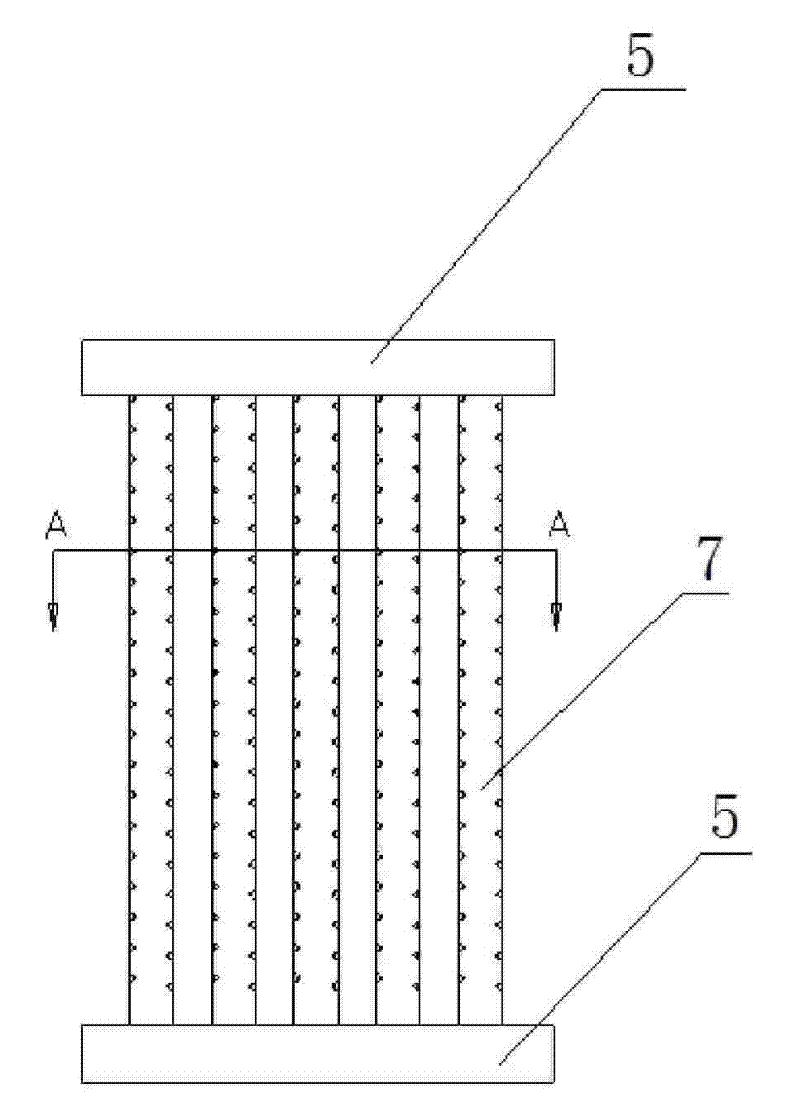
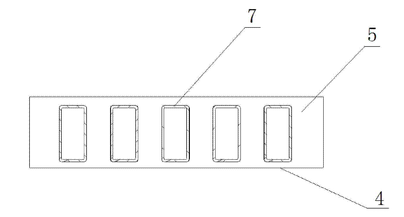
[0033] Such as Figure 1-Figure 4 As shown, a biomass stove burner includes a biomass furnace 1 and an air burner 4. The biomass furnace 1 is provided with a charging door 2 and a flue gas outlet 3. The two ends of the air burner 4 are connected to the biomass furnace 1 The inner sides of the air burner 4 are connected to each other, and the two sides of the air burner 4 are separated from the inner wall of the biomass furnace 1 . The air burner 4 is arranged between the charging door 2 and the flue gas outlet 3 . Air burner 4 is made up of support 5 and air supply pipe 7, and air support 4 is " work " shape, and its two ends are support 5, and air supply pipe 7 is vertically connected with support 5 and is evenly distributed on support 5. The air supply pipe 7 is elongated tube shape, has 5, leaves gap between two supply air pipes 7, is provided with some air supply ports on the air supply pipe 7, and the air supply ports are round holes or square holes evenly distributed. ...

Embodiment 2

[0038] In this embodiment, the cross-section of the air supply pipe 7 is a rectangle with four corners with guide angles, a secondary air supply port 71 is provided in the middle of the bottom, and a third air supply port 72 is respectively provided on the guide angles of the upper left corner and the upper right corner, as shown in FIG. Image 6 Shown, others are with embodiment 1. The section of the air supply pipe 7 in this embodiment may also be trapezoidal.

Embodiment 3

[0040] In this embodiment, the cross-section of the air supply pipe 7 is a rectangle with guide angles on the top and both sides, and two secondary air supply ports 71 are arranged on the bottom side, and the guide angles of the upper left corner and the upper right corner are respectively provided with Three air supply ports 72, such as Figure 7 Shown, others are with embodiment 1. The section of the air supply pipe 7 in this embodiment may also be trapezoidal.


PUM


Abstract

The invention relates to a biomass furnace combustor and a combustion method thereof. The biomass furnace combustor comprises a biomass furnace and an air combustion supporting device, wherein the biomass furnace is provided with a charging door and a smoke outlet, both ends of the air combustion supporting device are connected with the inner side of the biomass furnace, and the two lateral facesof the air combustion supporting device are separated from the inner wall of the biomass furnace; and the air combustion supporting device mainly comprises a bracket and at least two air replenishingpipes, both ends of each of the air replenishing pipe are connected with the bracket, a gap is kept between the air replenishing pipes, a plurality of air replenishing openings are arranged on the air replenishing pipes, at least one air inlet is arranged on the bracket, and air passages connected with the mouths of the air replenishing pipes are arranged in the bracket. The biomass furnace combustor is installed above an industrial biomass semi-gasification stove, and enables coal or biomass solid fuel to be directly combusted to generate a great amount of combustible gas and particle black carbon; and when passing through the air combustion supporting device, the combustible gas and the particle black carbon can be thoroughly and completely combusted, black smoke can be eliminated, and the thermal energy conversion rate of the fuel can be increased. The invention saves the fuel cost, protects the environment, etc.

Description

technical field [0001] The invention relates to a device for increasing the combustion efficiency of a biomass furnace, in particular to a biomass furnace burner, which belongs to the technical field of combustion equipment. Background technique [0002] In recent years, the development and utilization of biomass energy has been gradually promoted and applied. In the early 1990s, household biomass gasifiers appeared on the market. Generally, downdraft gasifiers are used, and the fuel is sawdust, bulk Broken branches, straw, corncobs, etc. have the advantage of being used for multiple times as a filler, but the structure is relatively complicated, including furnaces (silos and gasification chambers), blowers, pipes, valves, and stoves, etc., and the price is relatively high. The problem is that a higher level of tar is produced, and the oil and water come out together. The flue gas formed due to the lack of combustion-supporting air when crop straws are burned not only pollu...

Claims


Application Information

Patent Timeline
Patent Type & Authority Patents(China)
IPC IPC(8): F23C5/08C10J3/60F23L9/00
CPCY02E20/18
Inventor 杜文庆
Owner 宁波双翼能源科技有限公司
Why Eureka
Try Eureka