Manufacture process of valve core

A manufacturing process and valve core technology, which is applied in the field of valve core manufacturing process, can solve the problems of large processing volume, low production efficiency, and long time consumption, so as to increase the crystallization density of materials, improve the quality of finished products, and prolong the service life Effect

A manufacturing process and valve core technology, which is applied in the field of valve core manufacturing process, can solve the problems of large processing volume, low production efficiency, and long time consumption, so as to increase the crystallization density of materials, improve the quality of finished products, and prolong the service life Effect

CN101649913AInactive Publication Date: 2010-02-17CIXI LONGSHAN AUTOMOBILE PART

Image

  • Manufacture process of valve core
  • Manufacture process of valve core
  • Manufacture process of valve core

Examples


Embodiment Construction

[0031] The manufacturing process of the valve core of the present invention will be described in further detail below in conjunction with the accompanying drawings and specific embodiments, but the present invention is not limited to the following specific embodiments.

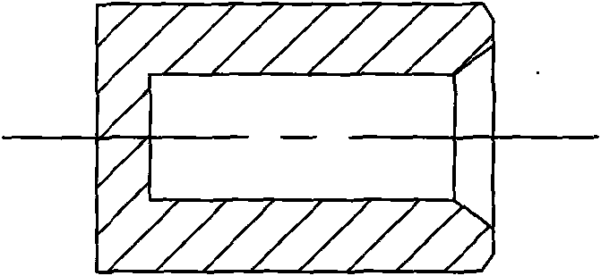
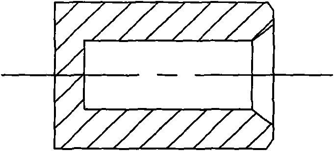
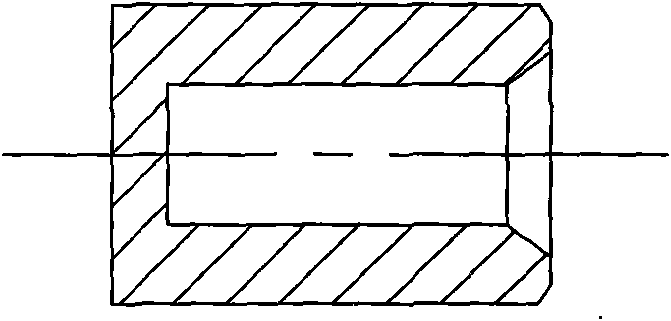
[0032] Such as figure 1 Shown, the manufacturing process of spool of the present invention, it comprises the following steps:

[0033] a. Calculate the mass and volume of the rough billet according to the quality of the finished product and the quality of the machining allowance, select round bar steel, convert the length of the rough billet according to the volume and diameter of the rough billet, and then blank according to the length. In actual operation, people select the volume of the machining allowance based on experience, and then multiply it by the density of the workpiece during machining to calculate the quality of the machining allowance. The volume of the rough billet is calculated by dividing the...


PUM


Abstract

The invention discloses a manufacture process of a valve core. The manufacture process comprises the following steps: a, converting the mass and the volume of a crude blank according to the mass and the process redundancy of a finished product; selecting cylindrical steel sheets; converting the length of the crude blank according to the volume and the diameter of the crude blank; then, blanking according to the length; b, using a cold header to carry out the cold heading treatment of a blanked workpiece; c, roughly machining an outer circle to ensure that an inner circumference surface and anouter circumference surface of the workpiece are concentric; d, roughly machining the end surface so that the workpiece basically achieves the length size requirement; e, punching holes by a punch; f,finely machining and chamfering the outer circle and the end surface; g, reaming and chamfering; and h, grinding the outer circle. The manufacture process of the valve core can enable the product tohave good quality and long service life, and has high production efficiency, little material waste and low production cost.

Description

technical field [0001] The invention relates to the field of auto parts, in particular to a manufacturing process for a valve core on an automobile ignition switch. Background technique [0002] The specific steps of the manufacturing process of the spool of the prior art are as follows: [0003] a. Select the cast round rod with a diameter slightly larger than the finished product, and blank it with a length slightly longer than the finished product; [0004] b. Use a drilling machine to drill a center hole on the workpiece processed in step a and use an instrument lathe to ream and chamfer the drilled workpiece; [0005] c. Use an instrument lathe to rough turn the outer circle of the workpiece after step b to ensure that the inner and outer peripheral surfaces of the workpiece are concentric; [0006] d. Use an instrument lathe to rough turn the end face of the workpiece processed in step c, so that the workpiece basically meets the length and dimension requirements; ...

Claims


Application Information

Patent Timeline
17 Feb 2010
Publication
CN101649913A
IPC
F16K3/30
Inventors
叢汀; 陆钂荫