Orthogonal transducer type cylindrical traveling-wave ultrasonic motor vibrator

An ultrasonic motor, cylindrical technology, applied in the direction of generator/motor, piezoelectric effect/electrostrictive or magnetostrictive motor, electrical components, etc., can solve the problem of reducing the mechanical output capacity and controllability of ultrasonic motors, Problems such as the limitation of the mechanical output capacity of the ultrasonic motor and the distortion of the vibration trajectory of the particle on the surface of the vibrator have achieved the effects of improving the mechanical output capability and controllability, avoiding the distortion of the vibration trajectory, and flexible design

Inactive Publication Date: 2010-02-17
HARBIN INST OF TECH
0 Cites 1 Cited by

AI-Extracted Technical Summary

Problems solved by technology

[0003] Due to the simplicity of the excitation principle and the simplicity of the theoretical analysis method, most of the vibrators of piezoelectric ultrasonic motors are excited by the method of pasting piezoelectric ceramic sheets with metal elastomers. This excitation method uses piezoelectric ceramic d 31 vibration mode, d 31 The vibration mode is the mode of stretching vibration of the ceramic sheet along the length direction. Due to the low tensile strength of the material in this vibration mode and the low efficiency of electromechanical coupling for energy conversion, an...

Method used

Described cylinder 1 inner wall evenly distributes a plurality of comb-shaped driving teeth 1-1 along the circumferential direction, comb-shaped driving teeth 1-1 and cylinder 1 are one piece, and a plurality of comb-shaped driving teeth 1-1 along the ...

Abstract

The invention relates to an orthogonal transducer type cylindrical traveling-wave ultrasonic motor vibrator belonging to the technical field of piezoelectric ultrasonic motors and solving the problemsthat the mechanical output capability of a motor is restricted because the prior ultrasonic motor vibrator adopts a metal elastomer to bond piezoelectric ceramic thin plates to excite, and the mechanical output capability and the controllability of an ultrasonic motor are reduced because a plurality of transducers are driven simultaneously. The orthogonal transducer type cylindrical traveling-wave ultrasonic motor vibrator comprises a cylinder and an orthogonal transducer, wherein the orthogonal transducer is formed by orthogonally connecting amplitude rods of a first transducer and a secondtransducer into a whole, both sides of each transducer flange are respectively connected with screw posts which are respectively screwed with the amplitude rods and a rear end cover, the screw posts among the flange, the amplitude rods and the rear end cover are respectively sleeved with piezoelectric ceramic plates and electrode plates, insulating sleeves are arranged among the piezoelectric ceramic plates, the electrode plates and the screw posts, and a plurality of comb-shaped driving teeth are evenly distributed on the inner wall of the cylinder along a circumferential direction. The orthogonal transducer type cylindrical traveling-wave ultrasonic motor vibrator is used for the field of manufacturing ultrasonic motors.

Application Domain

Piezoelectric/electrostriction/magnetostriction machines

Technology Topic

CantileverUltrasonic motor +7

Image

  • Orthogonal transducer type cylindrical traveling-wave ultrasonic motor vibrator
  • Orthogonal transducer type cylindrical traveling-wave ultrasonic motor vibrator
  • Orthogonal transducer type cylindrical traveling-wave ultrasonic motor vibrator

Examples

  • Experimental program(3)

Example Embodiment

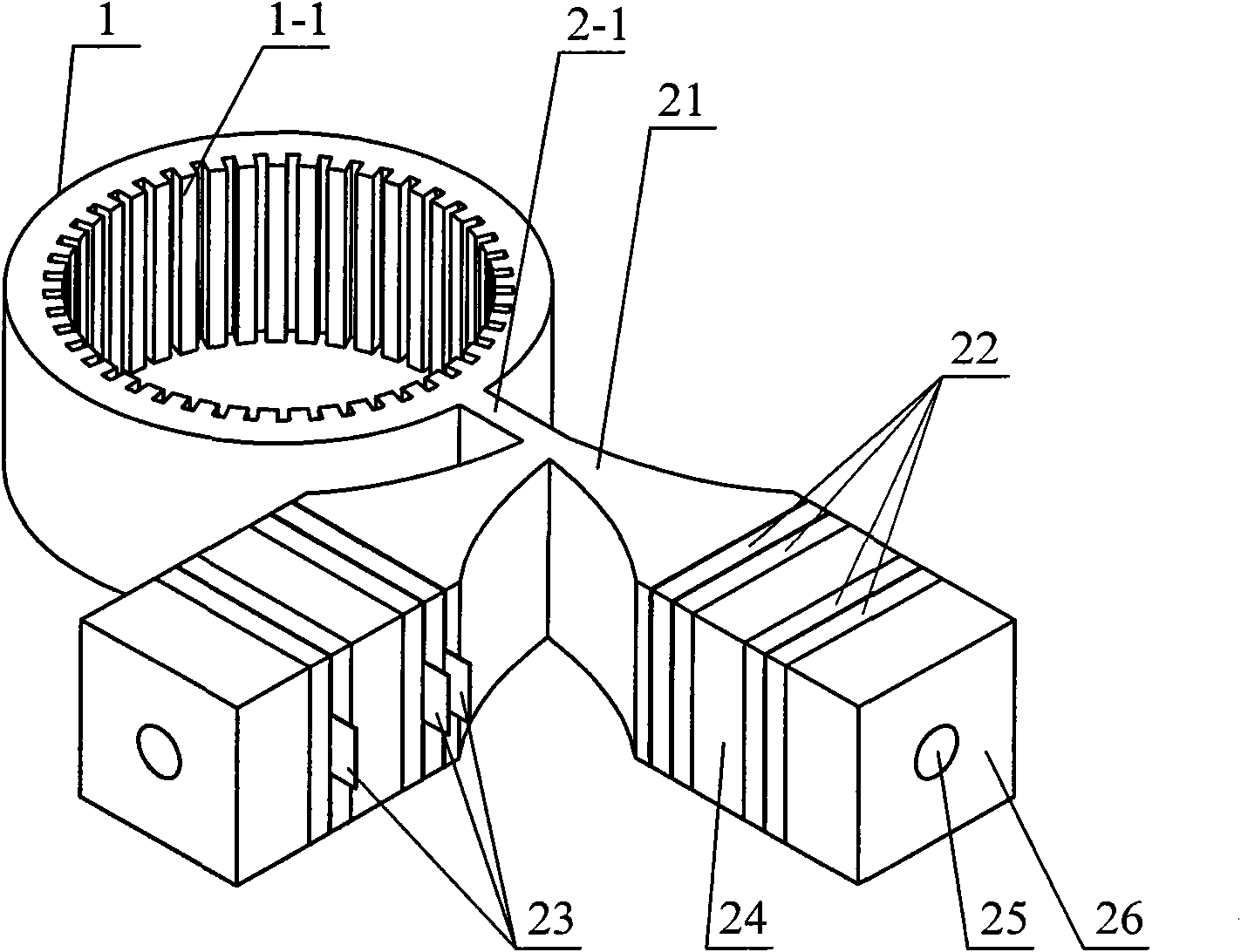
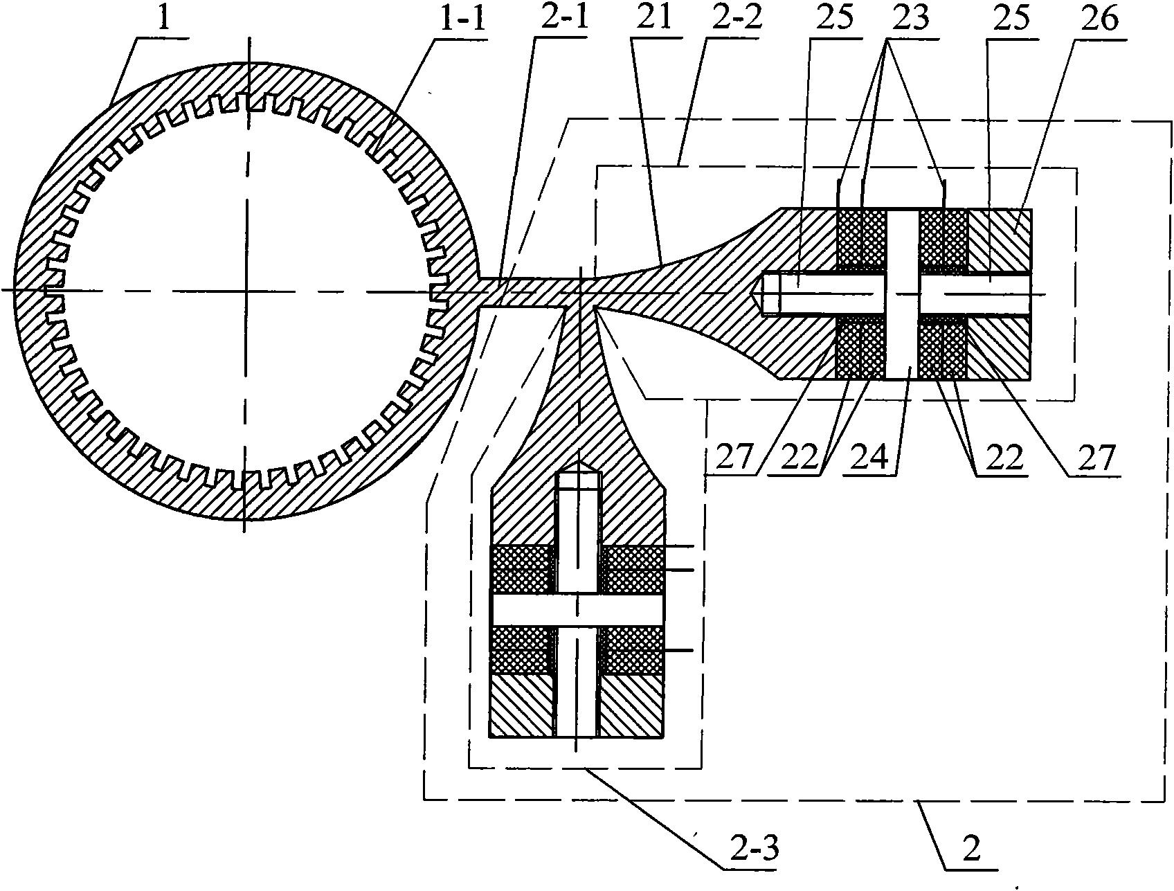
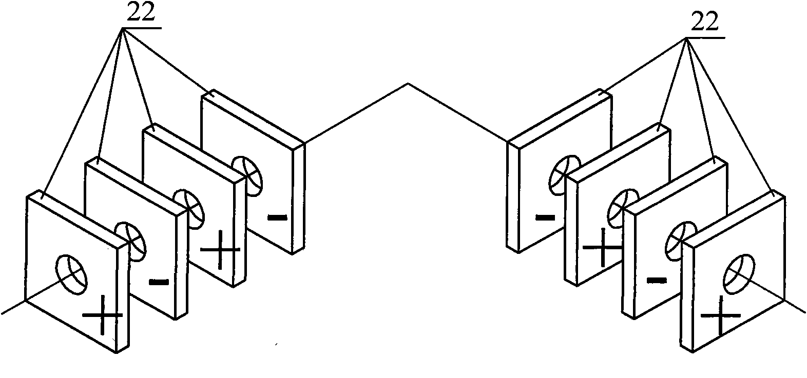
[0014] Specific implementation mode one: the following combination Figure 1 to Figure 6 Describe this embodiment, this embodiment comprises cylinder 1, and it also comprises positive transducer 2, and positive transducer 2 is made up of cantilever 2-1, first transducer 2-2 and second transducer 2-3 The first transducer 2-2 and the second transducer 2-3 are respectively composed of a horn 21, four piezoelectric ceramic sheets 22, three electrode sheets 23, a flange 24, two studs 25, The rear end cover 26 is composed of two insulating sleeves 27,
[0015] The horn 21 is a quadrangular prism whose cross-section is rectangular and tapered from one end to the other. The small end surfaces of the two horns 21 of the first transducer 2-2 and the second transducer 2-3 are Orthogonally integrated, the intersecting small end surfaces of the two horns 21 are integrated with one end surface of the cantilever 2-1, the other end surface of the cantilever 2-1 is integrated with the outer surface of the cylinder 1, the cantilever 2 -1 is a cuboid;
[0016] Both sides of the center of the flange 24 are respectively connected to one end of a stud 25, the other end of the one stud 25 is screwed into the center of the large end face of the horn 21, the other end of the other stud 25 is connected to the rear end The cover 26 is screwed together, and the stud 25 between the horn 21 and the flange 24 and the stud 25 between the flange 24 and the rear end cover 26 are respectively covered with two piezoelectric ceramic sheets 22, and the horn 21 and the piezoelectric ceramic sheet 22 and between every two adjacent piezoelectric ceramic sheets 22 are respectively fixed with an electrode sheet 23, and are respectively arranged between the piezoelectric ceramic sheet 22 and the electrode sheet 23 and each stud 25 There is an insulating sleeve 27;
[0017] Each piezoelectric ceramic sheet 22 is polarized along the thickness direction, and the polarization direction of every two adjacent piezoelectric ceramic sheets 22 is opposite to that of the two adjacent piezoelectric ceramic sheets 22 to the flange 24;
[0018] The inner wall of the cylinder 1 is evenly distributed with a plurality of comb-shaped driving teeth 1-1 along the circumferential direction, the comb-shaped driving teeth 1-1 and the cylinder 1 are integrated, and the multiple comb-shaped driving teeth 1-1 are The axial direction is parallel to the central axis; in this embodiment, the height of the cylinder 1 is the same as the thickness of the positive energy exchanger 2, which can make the process simpler in the actual processing.
[0019] Working principle: when the piezoelectric ceramic sheet in the vibrator of the present invention is excited by a two-phase AC voltage signal with the same amplitude, the frequency is the resonant frequency of the vibrator itself, and the phase difference is +90°, the longitudinal vibration of the piezoelectric ceramic sheet is used to achieve circular vibration. Cylinder 1 excites two bending vibration modal responses with equal amplitude and a difference of π/2 in time and space. The two bending vibration modal responses are superimposed on cylinder 1 to form traveling waves. The two basic vibration modes Modes such as Figure 5 , Image 6 As shown, the particles on the surface of the comb-shaped driving teeth 1-1 generate elliptical motion trajectories, and the macroscopic motion output of the rotor is realized through the frictional coupling between the comb-shaped driving teeth 1-1 and the rotor. If the phase difference of the two excitation signals is adjusted to -90°, the direction of the traveling wave can be changed, and the reverse motion of the motor rotor can be realized finally.
[0020] When the positive transducer type cylindrical traveling wave ultrasonic motor vibrator of this embodiment is applied, refer to Figure 4 As shown, the electrode piece 23 between each horn 21 and the piezoelectric ceramic piece 22 is connected to the common terminal V of the driving power supply 0 connection, the electrode sheet 23 between every two adjacent piezoelectric ceramic sheets 22 in the first transducer 2-2 is connected to the driving signal V 1 connection, the electrode sheet 23 between every two adjacent piezoelectric ceramic sheets 22 in the second transducer 2-3 and the driving signal V 2 connect.

Example Embodiment

[0021] Embodiment 2: This embodiment differs from Embodiment 1 in that the cross-sections of the piezoelectric ceramic sheet 22 and the flange 24 are rectangular. Other components and connections are the same as those in Embodiment 1.

Example Embodiment

[0022] Embodiment 3: The difference between this embodiment and Embodiment 1 is that the cross-sections of the piezoelectric ceramic sheet 22 and the flange 24 are circular. Other components and connections are the same as those in Embodiment 1.

PUM

no PUM

Description & Claims & Application Information

We can also present the details of the Description, Claims and Application information to help users get a comprehensive understanding of the technical details of the patent, such as background art, summary of invention, brief description of drawings, description of embodiments, and other original content. On the other hand, users can also determine the specific scope of protection of the technology through the list of claims; as well as understand the changes in the life cycle of the technology with the presentation of the patent timeline. Login to view more.

Similar technology patents

Method and apparatus of transmitting information in wireless communication system

ActiveUS20110170489A1improve performanceeffectively transmit information
Owner:LG ELECTRONICS INC

Storage system and data processing system

InactiveUS20060031647A1avoid affect communicationimprove performance
Owner:HITACHI LTD

Classification and recommendation of technical efficacy words

Why Eureka
Try Eureka