Insulation layer for use in thermal insulation, insulation and method of manufacturing such

A technology for insulating layers and insulating parts, which is applied in the field of manufacturing insulating parts and can solve the problems of affecting vacuuming time, long production time, and reduced insulation efficiency.

Inactive Publication Date: 2010-02-17
FIDENS HLDG
View PDF0 Cites 3 Cited by
  • Summary
  • Abstract
  • Description
  • Claims
  • Application Information

AI Technical Summary

Problems solved by technology

[0007] Multilayer insulation according to the prior art leads to long production times when the surrounding vacuum space is evacuated
The dense aluminum foil layer also affects the production time, i.e. in a negative way affects the time required for evacuation
Also, insulation efficiency is reduced due to convective heat transfer caused by water bonded to the glass fibers

Method used


Image

  • Insulation layer for use in thermal insulation, insulation and method of manufacturing such
  • Insulation layer for use in thermal insulation, insulation and method of manufacturing such
  • Insulation layer for use in thermal insulation, insulation and method of manufacturing such

Examples


Embodiment Construction

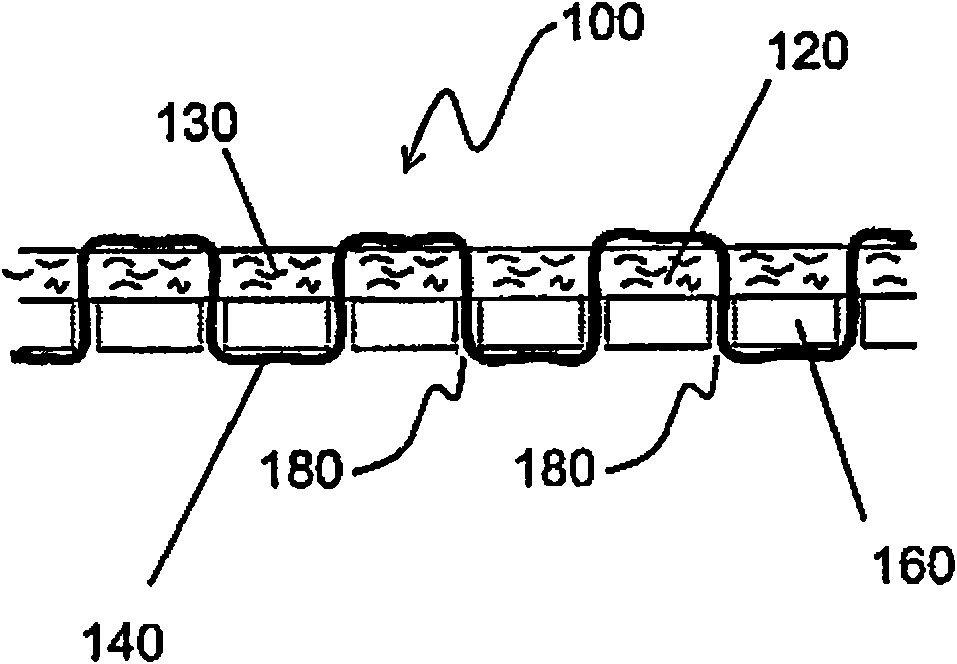
[0037] figure 2 An embodiment of an insulating layer 100 according to the invention is shown. The insulating layer 100 includes a radiation shield 160 for reflecting thermal radiation and an insulating material 120 . Radiation shield 160 is attached to isolation material 120 by fastening material 140 . A plurality of apertures 180 are provided on the radiation shield 160 . The insulating material 120 is composed of a fibrous material including a plurality of fibers 130 . The fastening material 140 consists of a thread that just passes through the porous insulating material 120 and the holes 180 provided on the radiation shield 160 . Thus, the isolation material 120 is sewn onto the radiation shield 160 . The insulating layer 100 is disposed in a vacuum.

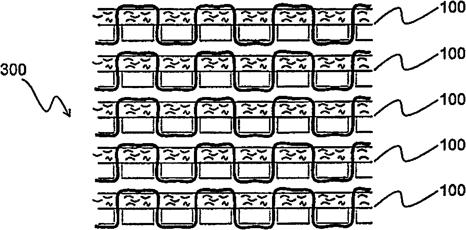
[0038] exist image 3 , showing according to figure 2 The five insulating layers 100 form an insulating member 300, also referred to as a multilayer insulating member. The insulating layer 100 is arranged such that ...


PUM


Abstract

The present invention relates to an insulating layer (100) for use in thermal insulation, comprising a radiation shield (160) for reflecting thermal radiation and a spacer material (120) which is attached to the radiation shield (160) by means of a fastening material (140), from which insulating layer (100) the air has been evacuated. The insulating layer (100) is characterised in that said radiation shield (160) comprises a plurality of through holes (180). The present invention also relates to an insulation for thermal insulation of an object as well as a method of manufacturing such an insulation.

Description

technical field [0001] The present invention relates to insulating layers for use in thermal insulation. The invention also relates to an insulating element for the thermal insulation of objects and a method for the manufacture of such an insulating element. Background technique [0002] Heat transfer from any object to its surroundings is caused by convection, conduction and radiation. To avoid this heat transfer, thermal insulation is usually required. Insulation of a simple structure for reducing heat transfer is used, for example, in warm or cold beverage containers such as In such containers, an enclosed vacuum space isolates the contents from the surrounding environment. Since the vacuum reduces heat transfer to only heat radiation, there is no convection or conduction induced heat transfer. Thus, an insulating effect is obtained which allows the beverage content in the container to maintain its temperature. [0003] When the application is more complex, there ar...

Claims


Application Information

Patent Timeline
Patent Type & Authority Applications(China)
IPC IPC(8): F17C13/00F16L59/065F17C3/08
CPCF16L59/065F17C13/00F17C2203/0308F17C2260/031F16L59/08F17C2203/035F17C2203/0391F17C2203/0624F17C2221/011F17C2221/012F17C2221/014F17C2260/033F17C2270/0727Y10T428/24331Y02E60/32F17C3/08F17C13/001
Inventor B·埃克伦德
Owner FIDENS HLDG
Why Eureka
Try Eureka