Source end coupling microstrip filter

A microstrip filter and source-end technology, applied in waveguide devices, electrical components, circuits, etc., can solve the problems of inflexible design and large size, and achieve the effect of small loss, small size and flexible design

Inactive Publication Date: 2010-03-03
SOUTH CHINA UNIV OF TECH
View PDF1 Cites 28 Cited by
  • Summary
  • Abstract
  • Description
  • Claims
  • Application Information

AI Technical Summary

Problems solved by technology

[0005] The purpose of the present invention is to provide a new type of source-side coupled microstrip filter in order to solve the technical problems that the existing microstrip filter cannot achieve better selectivity, and the volume is still large and the design is inflexible. Multiple controllable transmission zeros and two different source

Method used


Image

  • Source end coupling microstrip filter
  • Source end coupling microstrip filter
  • Source end coupling microstrip filter

Examples


Embodiment 1

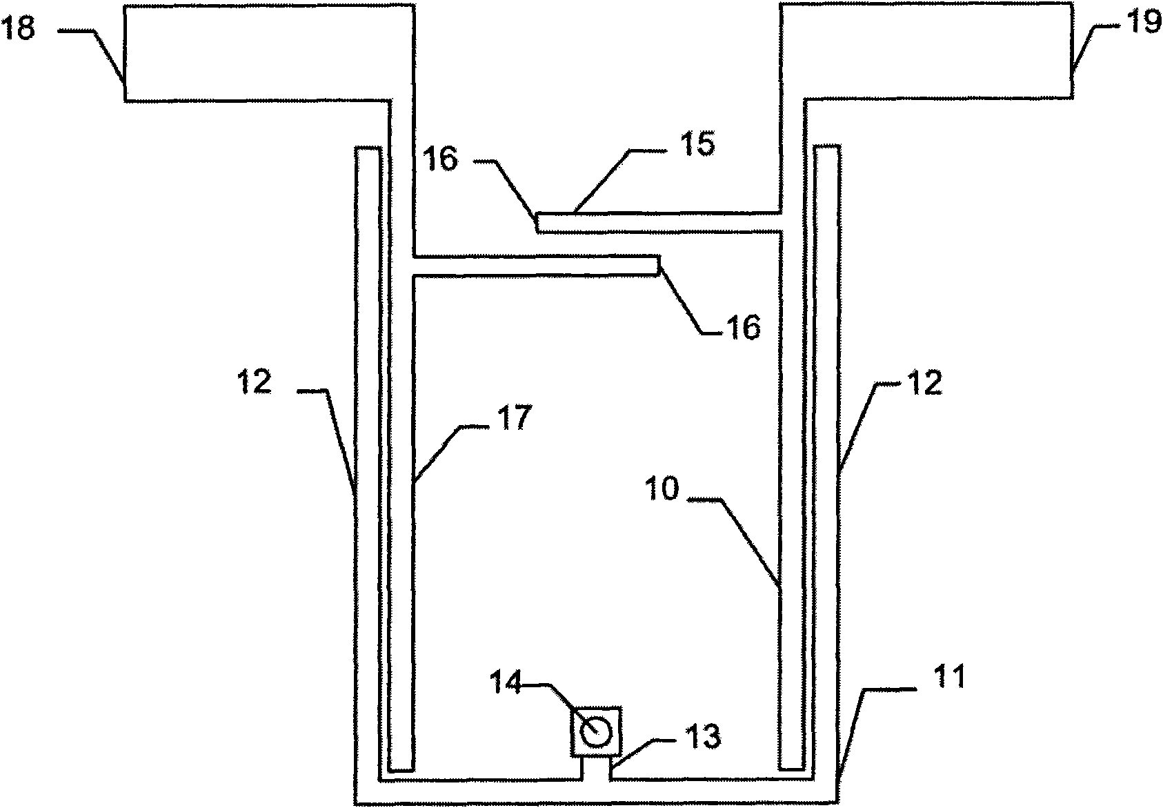
[0031] Such as figure 1As shown, this embodiment is a second-order source-coupled microstrip filter with multiple controllable transmission zeros, including a centrally symmetrical T-shaped resonator 11, an input coupling feeder 17, an output coupling feeder 10, and a A group of interdigitated coupling lines 15 arranged between the input coupling feeder and the output coupling feeder and perpendicular to the input coupling feeder and the output coupling feeder in the shaped resonator. The T-shaped resonator 11 includes two open-circuit branches 12 and a short-circuit branch 13, wherein the two open-circuit branches 12 form both sides of the U-shaped microstrip line; the short-circuit branch 13 is arranged at the bottom end of the U-shaped microstrip line, and the short-circuit The short-circuit end of the branch 13 is provided with a ground via 14, and the microstrip line is connected to the ground through the ground via 14 to form a short circuit. The input port 18 and the o...

Embodiment 2

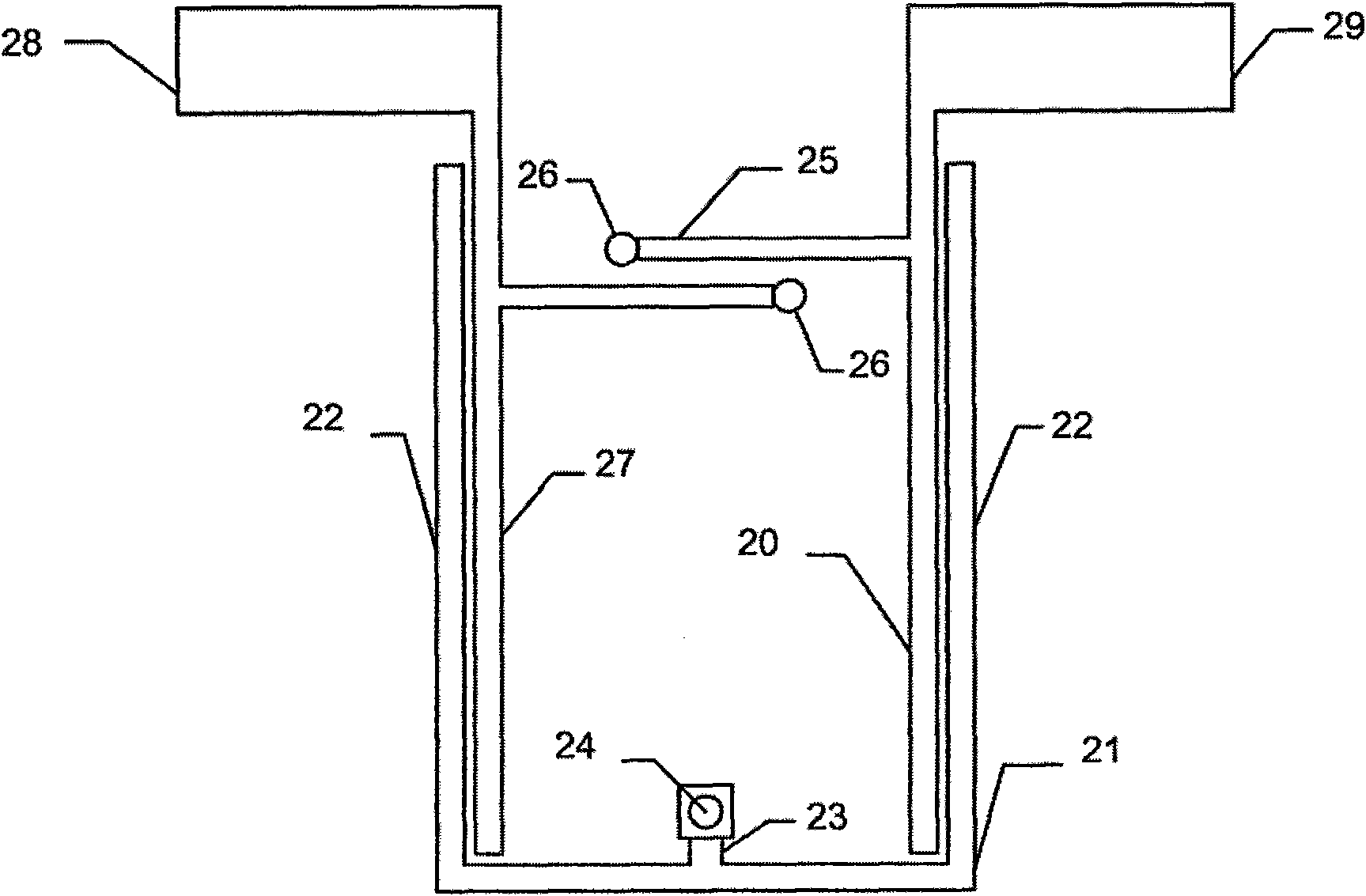
[0036] Such as figure 2 As shown, this embodiment is also a second-order source-coupled microstrip filter with multiple controllable transmission zeros, and is similar in structure to Embodiment 1: it includes a centrally symmetrical T-shaped resonator 21, an input coupling feeder 27, The output coupling feeder 20 and a group of interdigital coupling lines 25 located in the T-shaped resonator and arranged between the input coupling feeder 27 and the output coupling feeder 20 . The T-shaped resonator 21 includes two open-circuit branches 22 and a short-circuit branch 23, and the two open-circuit branches 22 form both sides of the U-shaped microstrip line; the short-circuit branch 23 is arranged on the bottom end of the U-shaped microstrip line, and the short-circuit branch The short-circuit end of 23 is provided with a ground via hole 24, and the U-shaped microstrip line is connected to the ground through the ground via hole 24 to form a short circuit. The difference from Emb...

Embodiment 3

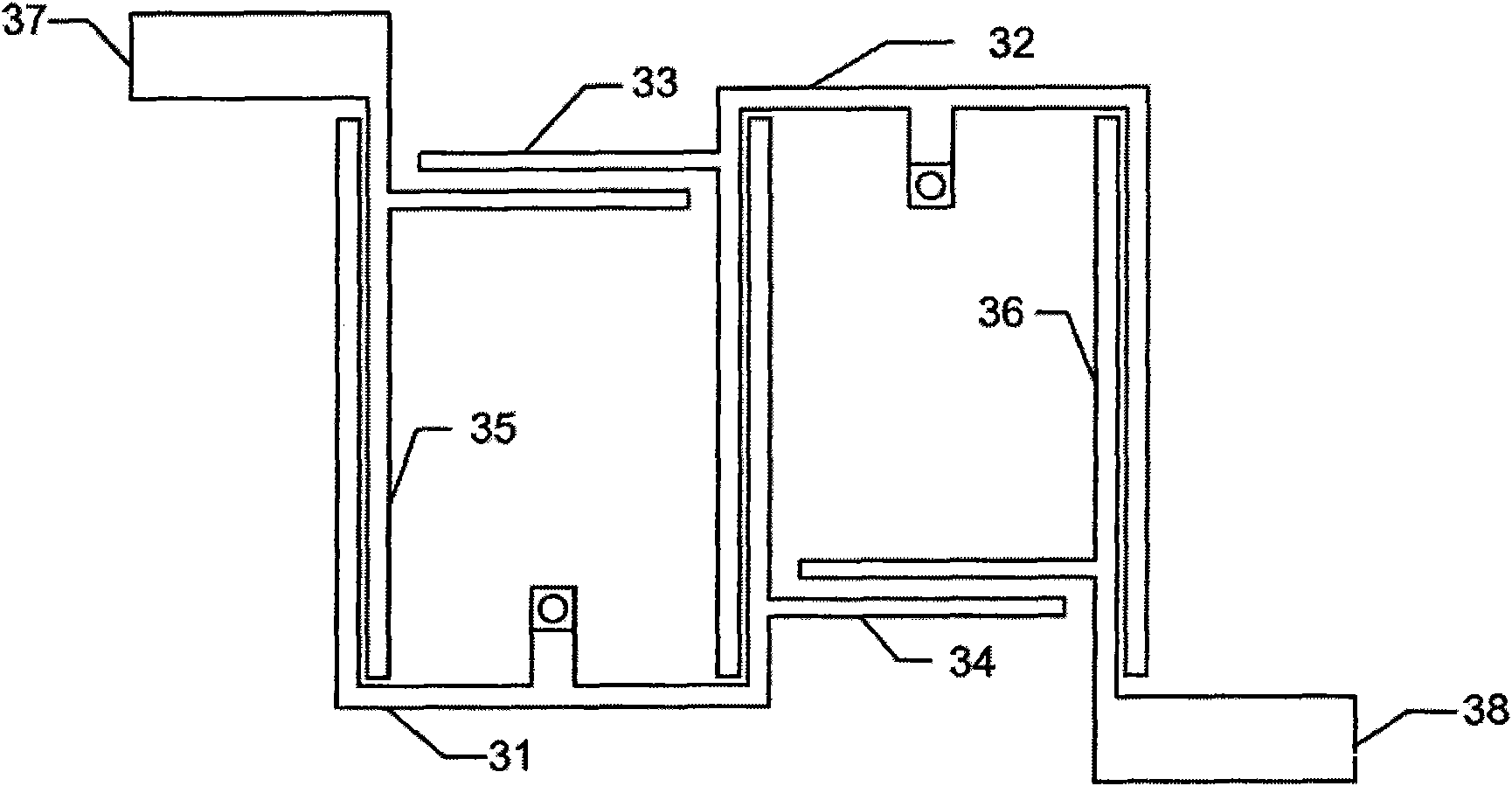
[0039] Such as image 3 As shown, this embodiment is a fourth-order source-side coupled microstrip filter, including a first T-shaped resonator 31 and a second T-shaped resonator 32 embedded in a coupling cascade, and a first group of interdigitated coupling lines 33, a second T-shaped resonator Two sets of interdigitated coupling lines 34 , input coupling feeders 35 , and output coupling feeders 36 . The first group of interdigitated coupling lines 33 is provided with two interdigitated coupling lines, located in the first T-shaped resonator 31, and arranged between the input coupling feeder 35 and the open-circuit branch of the second T-shaped resonator 32; The group of interdigitated coupling lines 34 has two interdigitated coupling lines, located in the second T-shaped resonator 32 , and arranged between the output coupling feeder 36 and the open branch of the first T-shaped resonator 31 . Wherein the first T-shaped resonator 31 is coupled with the output coupling feeder ...


PUM


Abstract

The invention discloses a source end coupling microstrip filter which comprises a T-shaped resonator, an input coupling feed line, an output coupling feed line and an interfinger coupling line, wherein the T-shaped resonator is provided with two open-circuit branch sections and a short-circuit branch section, the two open-circuit branch sections form both sides of a U-shaped microstrip line, the short-circuit branch section is arranged at the bottom end of the U-shaped microstrip line, the short-circuit end of the short-circuit branch section is provided with a grounding through hole, and thesum of the lengths of the two open-circuit branch sections and the short-circuit branch section is a one half wavelength; the input coupling feed line and the output coupling feed line are coupled with the open-circuit branch sections at the inner sides of the open-circuit branch sections of the T-shaped resonator; and the interfinger coupling line is positioned in the T-shaped resonator and is arranged between the input coupling feed line and the output coupling feed line. The invention is provided with a plurality of controllable transmission zero points and has the advantages of flexible design, small volume, small insertion loss and the like.

Description

technical field [0001] The invention relates to the field of microwave microstrip filters, in particular to a multimode resonator and a source-end coupling microstrip filter with a source-end coupling structure. Background technique [0002] As the front-end equipment of the wireless communication system, there is an urgent need for high selectivity, small size, low cost, and flexible design of RF filters for efficient spectrum utilization. High selectivity means that the passband to stopband transition of the filter response is very rapid, that is, the transition band is very steep, and the stopband insertion loss should be as large as possible. Transmission zeros on both sides of the passband and in the stopband will greatly improve the selectivity of the filter. The transmission zero point is the notch point, which can be considered as the zero point on the frequency response curve. Transmission zeros can appear on one or both sides of the passband to improve out-of-ban...

Claims


Application Information

Patent Timeline
IPC IPC(8): H01P1/203
Inventor 褚庆昕范莉
Owner SOUTH CHINA UNIV OF TECH
Why Eureka
Try Eureka