Funnel-shaped valve piezoelectric pump and working method thereof

A piezoelectric pump and funnel-shaped technology, applied in the field of passive valve piezoelectric pumps, can solve the problems of unfavorable piezoelectric pump miniaturization, reliability improvement, difficulty in processing and installation, unstable work, etc., and achieve small energy loss and disturbance Effect of small size and efficiency improvement

Inactive Publication Date: 2010-03-10
NANJING UNIV OF AERONAUTICS & ASTRONAUTICS
View PDF1 Cites 12 Cited by
  • Summary
  • Abstract
  • Description
  • Claims
  • Application Information

AI Technical Summary

Problems solved by technology

[0005] At present, the flow pipe valve body mechanism includes spherical valves, membrane valves, cantilever beam valves and disc valves, etc. Since these valves must be installed in the pipeline or at the end of the flow pipe, the size to be done is very small, which requires processing and processing. It is difficult to install, and there are also disadvantages such as short life, unstable operation, and easy blockage, which is not conducive to the miniaturization of piezoelectric pumps and the improvement of reliability.

Method used


Image

  • Funnel-shaped valve piezoelectric pump and working method thereof
  • Funnel-shaped valve piezoelectric pump and working method thereof

Examples


Embodiment Construction

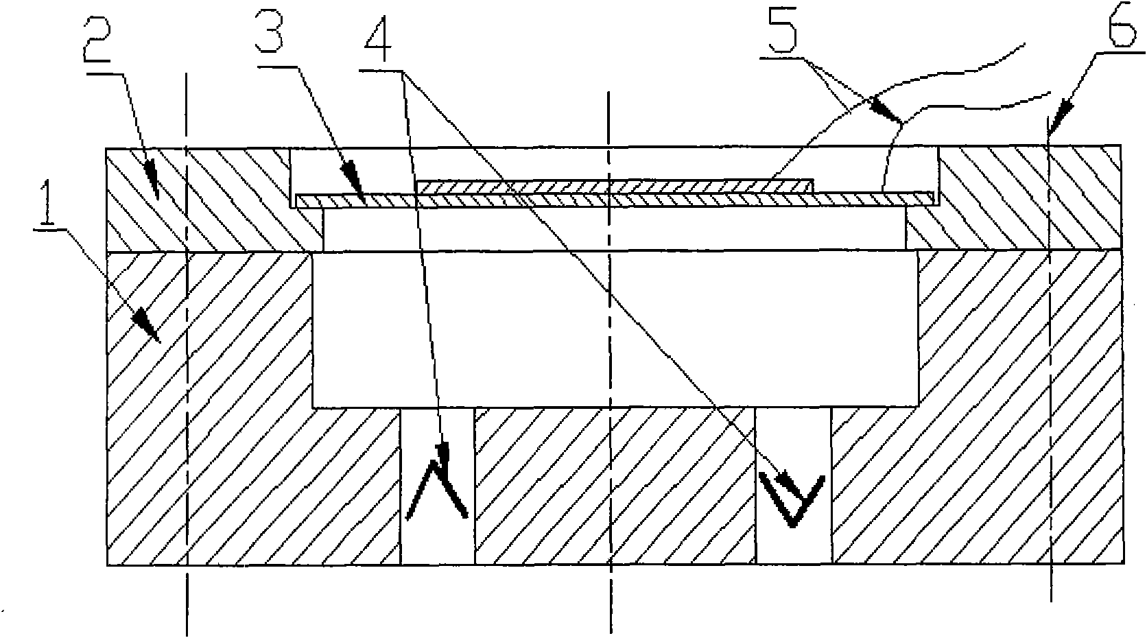
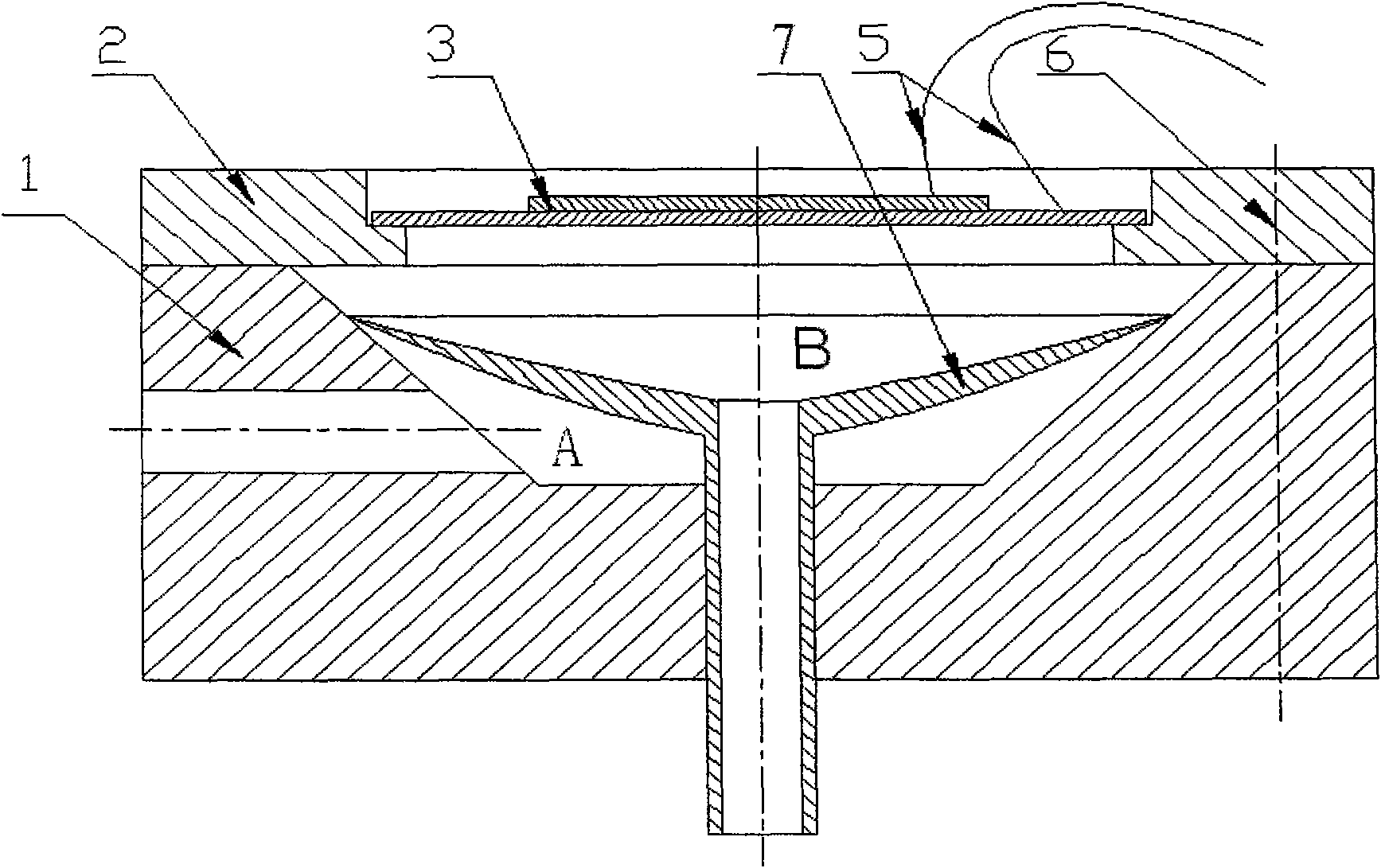
[0018] A new type of passive valve piezoelectric pump provided by the present invention-a funnel-shaped valve piezoelectric pump, the structure is as follows figure 2 As shown, the circumference of the circular piezoelectric vibrator 3 with wires is firmly supported on the stepped groove of the pump cover 2, the pump cover 2 and the pump body 1 are fastened together with 5 bolts (6 pieces), and the pump cavity of the pump body is funnel-shaped A through hole is opened on the side and bottom of the pump body. The side hole is the pump inlet. A funnel-shaped valve body 7 with a conduit is installed in the pump cavity. The angle of the funnel-shaped valve body is different from that of the funnel-shaped cavity. The chamber is divided into two chambers, A and B. The valve body is made of a material with good elasticity (such as: resin) into a funnel shape with a thick center and thin edges. A central hole is opened on it to connect with the conduit. The edge of the valve body is ...


PUM


Abstract

The invention relates to a funnel-shaped valve piezoelectric pump and a working method thereof, and belongs to the field of fluid machinery. A pump body (1) is provided with an inverted conical or round table-shaped pump cavity, a central passage and a lateral passage; a valve body consists of a valve core and a central conduit connected with the valve core; the valve core is also provided with anopen valve core inner cavity, and the valve core and the central conduit are combined to integrally form into a funnel shape; the edge of the valve core and the inner wall of the pump cavity form anedge valve port; and the pump cavity is divided into a cavity A and a cavity B by the valve core, wherein the inner wall of the pump cavity and the side wall of the valve core form the cavity A, and the inner wall of the valve core, the inner wall of the pump cavity, a pump cover and a piezoelectric vibrator surround into the cavity B. The edge of a funnel-shaped valve contacts the approximate points on the conical surface of a funnel-shaped cavity, the piezoelectric vibrator vibrates to lead the volume of the pump cavity B to periodically change, and a fluid only can flow into the pump cavityB from the pump cavity A through the boundary of the funnel-shaped valve and can not reversely flow, thereby performing the function of the valve, and achieving the purpose of miniaturization, simplification and convenient installation of the piezoelectric pump.

Description

technical field [0001] The funnel-shaped valve piezoelectric pump and its working method of the present invention belong to the field of fluid machinery, and in particular relate to a passive valve piezoelectric pump. Background technique [0002] If the volumetric piezoelectric pump is classified according to whether the valve body is present, it can be divided into two types: valved and valveless piezoelectric pumps. A valve is defined as a mechanical device that creates a disconnect between the pump chamber and the suction port or discharge port during at least one point in time during the suction and discharge of the pump. At present, most piezoelectric pumps with valves use moving parts installed in the lumen of the flow tube or at the end of the flow tube to control the opening and closing of the pipeline through the moving parts, so as to realize the conduction or blocking of the fluid. [0003] figure 1 A schematic diagram of a conventional valved piezoelectric pum...

Claims


Application Information

Patent Timeline
Patent Type & Authority Applications(China)
IPC IPC(8): F04B43/04F04B53/10
Inventor 张建辉郭宗信
Owner NANJING UNIV OF AERONAUTICS & ASTRONAUTICS
Why Eureka
Try Eureka