
LED lamp and heat dissipating structure thereof

A technology of LED lamps and heat dissipation structures, which is applied in lighting and heating equipment, cooling/heating devices of lighting devices, electrical components, etc., and can solve the problems of inconsistent heat dissipation requirements of LED lamps, increase in the number of heat pipes, and increase the manufacturing cost of heat dissipation fins, etc.

Inactive Publication Date: 2010-03-10
白豪
View PDF0 Cites 4 Cited by
  • Summary
  • Abstract
  • Description
  • Claims
  • Application Information

AI Technical Summary

Problems solved by technology

[0005] When heat pipes are used in the heat dissipation structure of LED lamps, it is often necessary to bend the heat pipes into "U" or "L" shapes to attach the heat-generating LED modules, which makes it impossible to use the heat pipes in a limited area. The number of heat pipes that can be configured is increased, and the heat cannot be evenly distributed to the cover, so that it does not meet the heat dissipation requirements of LED lamps; manufacturing cost

Method used


Image

  • LED lamp and heat dissipating structure thereof
  • LED lamp and heat dissipating structure thereof
  • LED lamp and heat dissipating structure thereof

Examples


Embodiment Construction

[0032] The detailed description and technical content of the present invention are described below with the accompanying drawings, but the attached drawings are only provided for reference and illustration, and are not intended to limit the present invention.

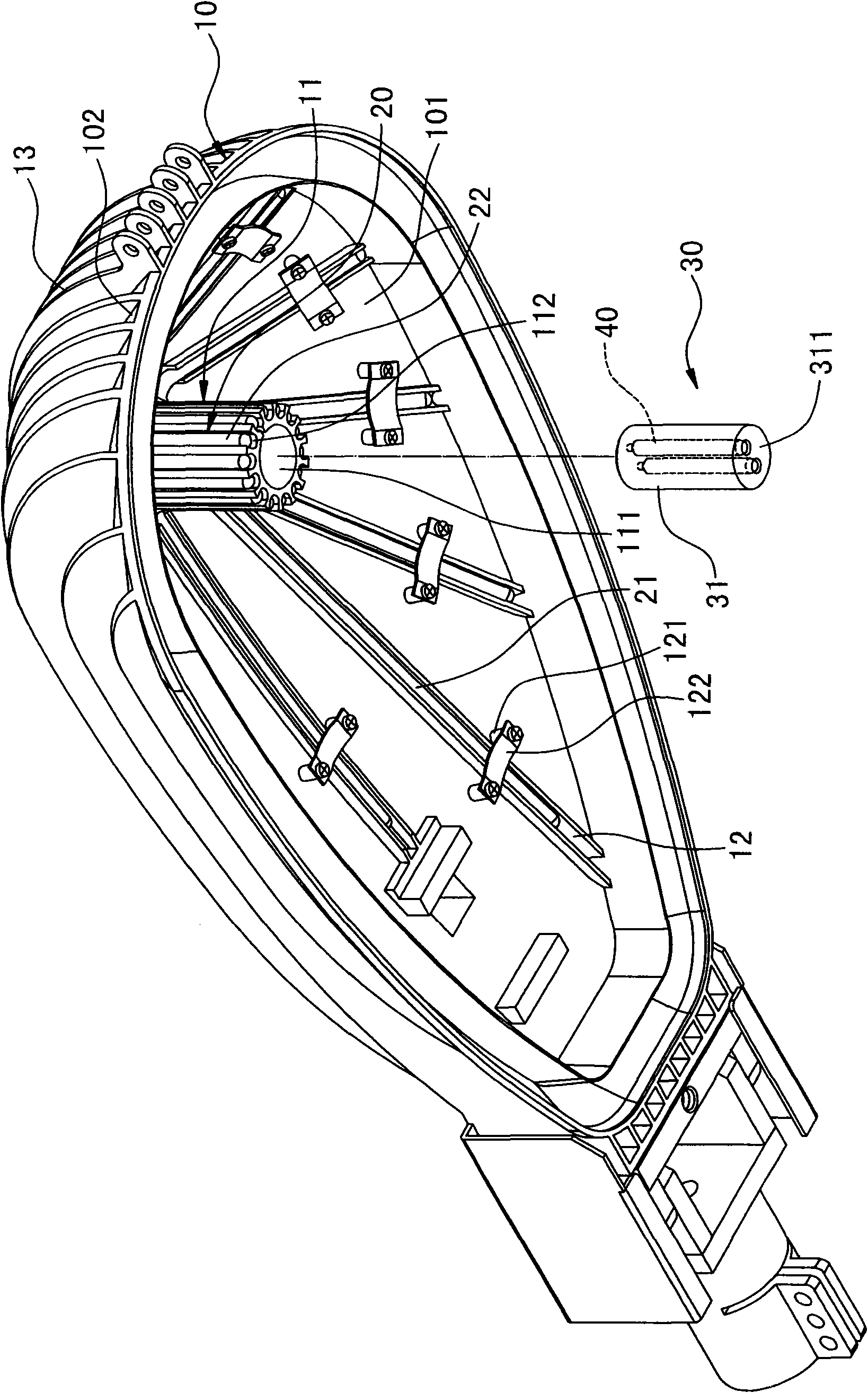
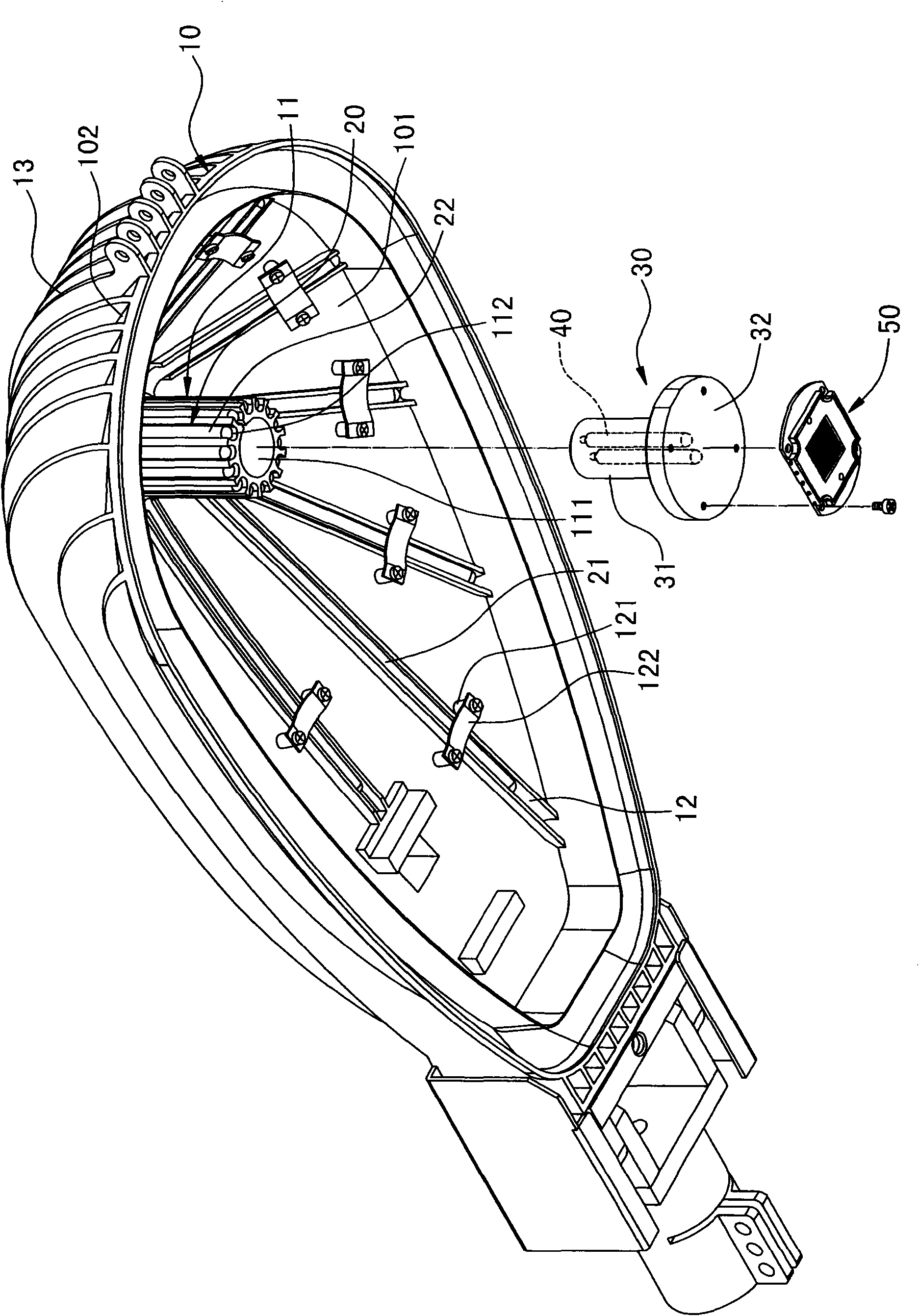
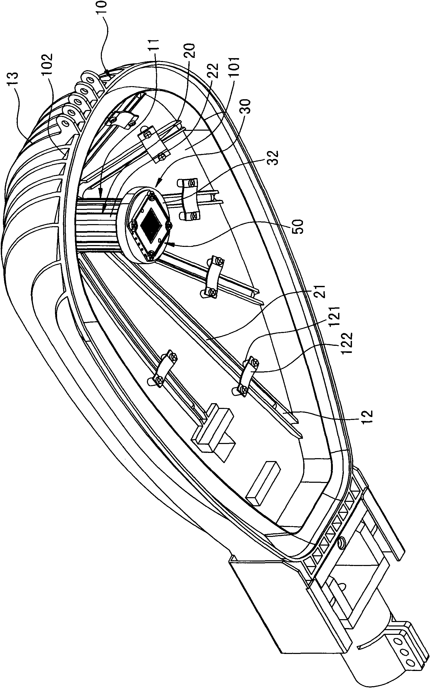
[0033] Please refer to figure 1 , is a three-dimensional combination diagram of the heat dissipation structure of the LED lamp of the present invention; it includes a lampshade 10, and a plurality of heat dissipation fins 13 can be formed on the outer surface, inner surface or inner and outer surfaces of the lampshade 10, and in this embodiment, a plurality of heat dissipation fins 13 are formed on the outer surface The surface 102 is provided with a plurality of heat dissipation fins 13, and a first heat conduction column 11 extends along the inner bottom surface 101 of the cavity. Holes 112, the axis lines of these accommodation holes 112 are parallel to the axis line of the first heat conduction column 11, in this em...


PUM


Abstract

The invention discloses an LED lamp and a heat dissipating structure thereof. The heat dissipating structure comprises a first heat conducting column extended along the inner bottom surface of a cavity of the heat dissipating structure, and a lampshade provided with a plurality of grooves; a peripheral ring of the first heat conducting column is provided with a plurality of accommodating holes andcombined with an evaporation end of a first heat pipe, and a condensation end of the first heat pipe is jointed with the groove of the lampshade; moreover, the heat dissipating structure comprises aheat conducting module provided with a second heat conducting column and a heat conducting plate, and the heat conducting module is mutually sleeved with the first heat conducting column by the secondheat conducting column to joint an LED luminous module to the heat conducting plate to form the LED lamp with the heat dissipating structure so as to remove the heat generated by the LED luminous module. By adopting the LED lamp provided by the invention, a radiating fin does not need to be additionally machined and the heat pipe is not needed to be inserted, so the manufacturing and machining cost for the radiating fin can be reduced, and the heat resistance can be reduced at the same time; and the first heat conducting column and the second heat conducting column are mutually sleeved to increase the elasticity and practicability on the structural design.

Description

technical field [0001] The invention relates to an LED lamp, in particular to an LED lamp provided with a heat pipe and a heat dissipation structure thereof. Background technique [0002] Light Emitting Diode (LED) has gradually replaced traditional light bulbs and is used in various lighting devices due to its low energy consumption, power saving, long service life, small size, and fast response. In order to increase its irradiation range and brightness, usually by combining multiple LEDs into an LED module. [0003] With the increase in the number of LEDs and the development of high-power LEDs, the heat generated by LED lamps is gradually rising. Therefore, how to design a structure with good heat dissipation for LED lamps has become the research of relevant people in this industry. one of the important subjects. [0004] On the other hand, because the heat pipe has many advantages such as high thermal conductivity, light weight, simple structure, no power consumption an...

Claims


Application Information

Patent Timeline
IPC IPC(8): F21V29/00F21V19/00H01L23/367H01L23/427F21Y101/02F21V29/508F21V29/71
Inventor 白豪
Owner 白豪
Learn More