Surface coating method of transmission mechanism

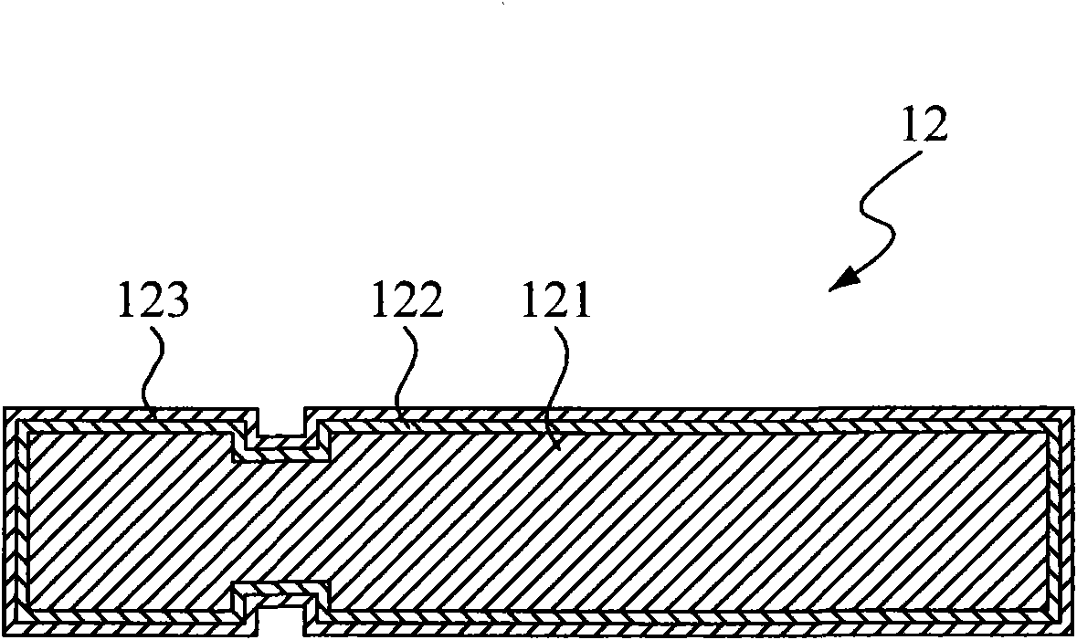
A transmission mechanism and surface coating technology, applied in the direction of gaseous chemical plating, metal material coating process, coating, etc., can solve the problem of broken bond ability, decreased wear resistance of coated drive shaft 12, and amorphous DLC film 123 Reduce surface hardness and other problems, achieve high surface hardness and avoid tempering effect

Inactive Publication Date: 2010-03-17
林玉雪
View PDF0 Cites 3 Cited by
  • Summary
  • Abstract
  • Description
  • Claims
  • Application Information

AI Technical Summary

Problems solved by technology

Obviously, due to the presence of argon-containing compounds, the covalent bonding ability of the amorphous DLC film 123 will be destroyed, th

Method used


Image

  • Surface coating method of transmission mechanism
  • Surface coating method of transmission mechanism
  • Surface coating method of transmission mechanism

Examples


Embodiment Construction

[0074] Due to the surface coating method provided by the invention, various transmission mechanisms (such as: bearings, transmission shafts, chains, spur gears, helical gears, bevel gears, cams, racks and transmission screws, etc.) can be widely coated. Various coating transmission mechanisms are manufactured, and the combinations thereof are too numerous to enumerate, so no more details are given here, and only one preferred embodiment is listed for specific illustration.

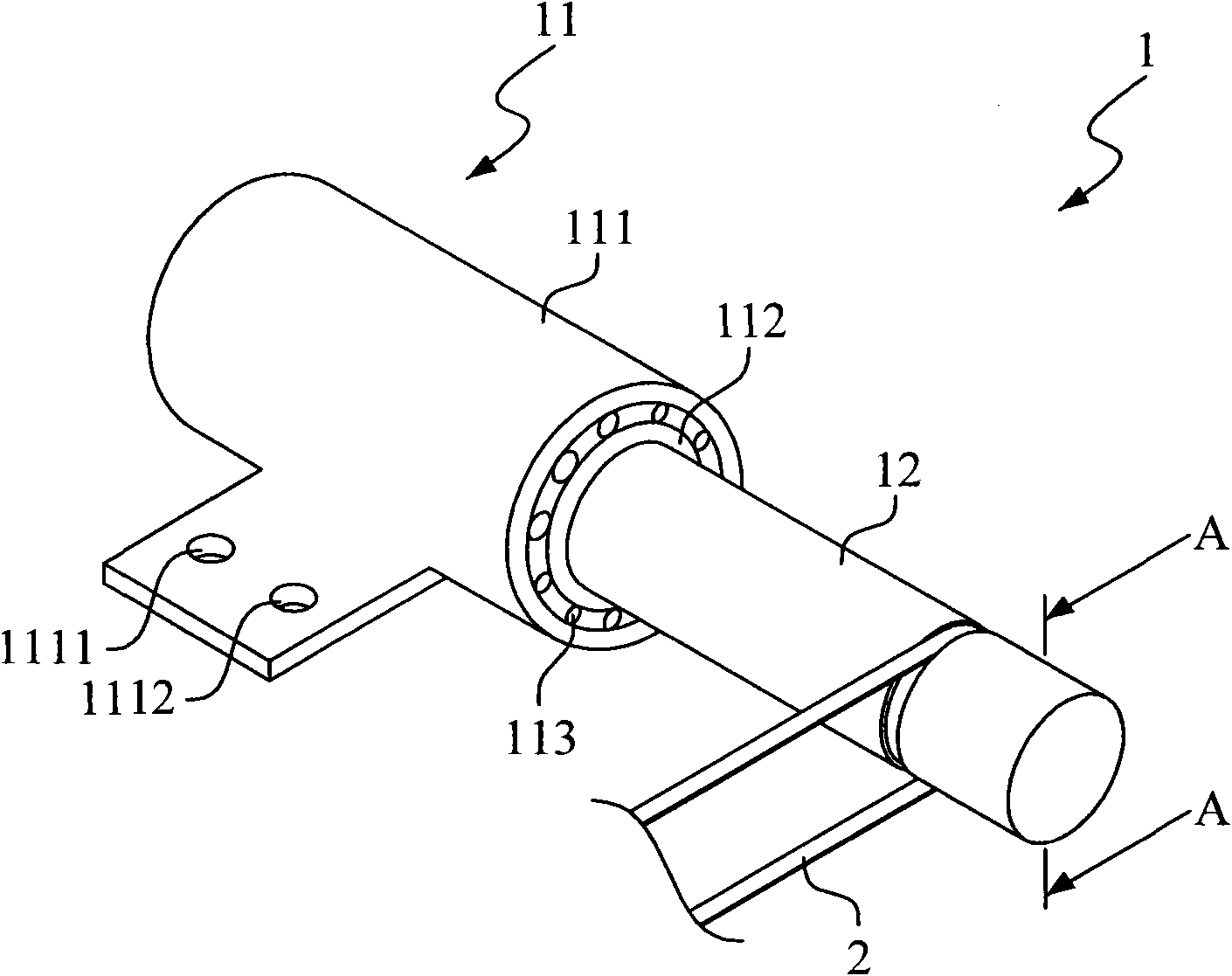
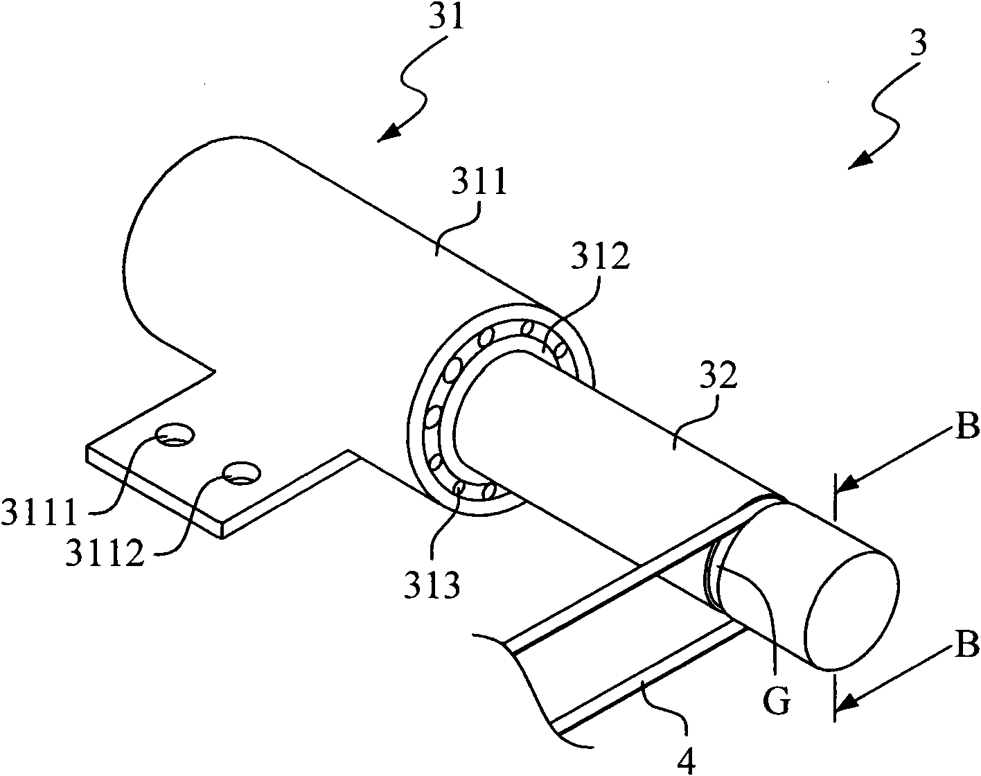
[0075] see image 3 , which shows a schematic diagram of a preferred embodiment of the present invention applicable to a transmission assembly. As shown in the figure, a transmission assembly 3 includes a coating bearing 31 and a coating transmission shaft 32 , and both the coating bearing 31 and the coating transmission shaft 32 can be regarded as a coating transmission mechanism.

[0076] The coated bearing 31 includes a fixed outer shaft 311 , a rotatable inner shaft 312 and a plurality of rollers 313 ...


PUM


Abstract

The invention provides a surface coating method of a transmission mechanism. The method comprises the following steps of: providing a transmission mechanism; cleaning the surface of the transmission mechanism; placing the transmission mechanism in a working environment in which hydrogen gas, tetra-methylsilane(TMS) and Si(CH3)4 gas are filled, applying an external electric power, of which the power is 800 to 1,500 watts, to generate a bias electric field in the working environment so as to form an attaching film on the surface of the transmission mechanism; forming a mixing film on the surfaceof the attaching film; and forming an amorphous diamond(diamond-like carbon, DLC) film on the surface of the mixing film, and finally manufacturing the coated transmission mechanism. In the mixing film, the content of the amorphous DLC materials increases with the distance from the transmission mechanism. By the method, the high surface hardness of the coated transmission mechanism is ensured, and the anti-wearing ability and life time of the coated transmission mechanism are improved.

Description

technical field [0001] The present invention relates to a manufacturing technology of a transmission mechanism, and in particular refers to a technology of coating a transmission mechanism surface to form a coated transmission mechanism. Background technique [0002] In general power devices, transmission mechanisms are unavoidably used during power transmission. Since the transmission mechanism must transmit power, in the process of power transmission, various degrees of wear will occur on the power transmission contact surface of the transmission mechanism. For example: on the contact surfaces between wheels, transmission shafts, bearings, racks, screws and (or) gears, the above-mentioned various degrees of wear will occur. Once the power transmission contact surfaces of these transmission mechanisms are worn to a certain extent, the lighter ones will cause unstable power transmission, and the severe ones will even make the entire transmission mechanism unable to perform ...

Claims


Application Information

Patent Timeline
IPC IPC(8): C23C16/32C23C16/42C23C16/455C23C16/52
Inventor 林玉雪
Owner 林玉雪
Why Eureka
Try Eureka