Miniature array electromagnet mounting assembly

A micro-array, electromagnet technology, applied in the direction of assembling printed circuits, electrical components, electrical components, etc. with electrical components, can solve the problems of too many mechanical transmission links, the bulk of the whole machine, and the complex structure of the placement head.

Inactive Publication Date: 2010-03-17
李建
View PDF0 Cites 15 Cited by
  • Summary
  • Abstract
  • Description
  • Claims
  • Application Information

AI Technical Summary

Problems solved by technology

[0003] In the existing technology at home and abroad, the structure of the placement head is complicated, and the volume of the placement head is relatively large, which makes the placement head heavy and clumsy, and finally leads to a correspondingly large volume of the whole machine. At present, the common problem that restricts the improvement of the placement head's working accuracy One is that there are too many mechanical transmission links and the difficulty and complexity of improving the precision of mechanical transmission

Method used


Image

  • Miniature array electromagnet mounting assembly
  • Miniature array electromagnet mounting assembly
  • Miniature array electromagnet mounting assembly

Examples


Embodiment Construction

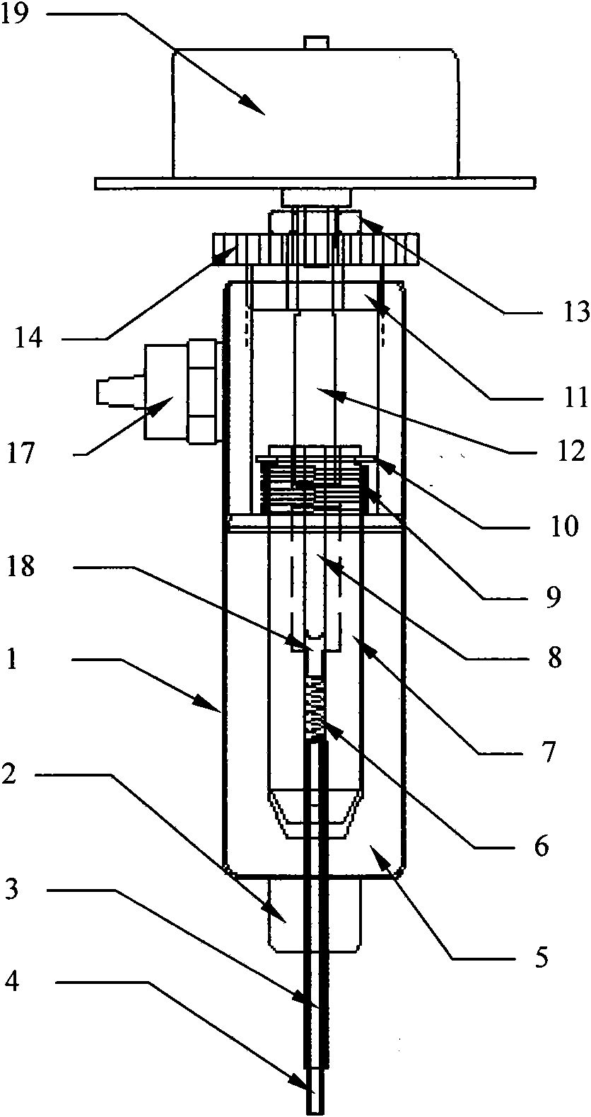
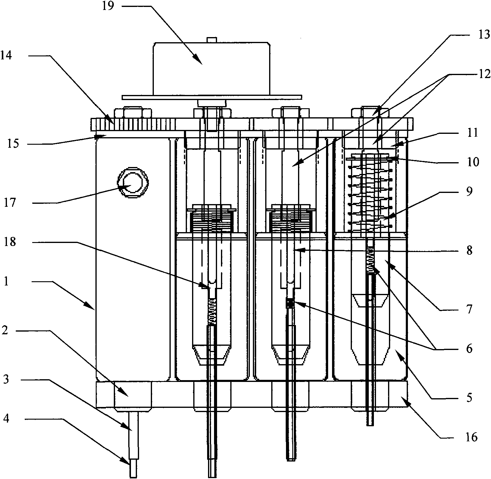
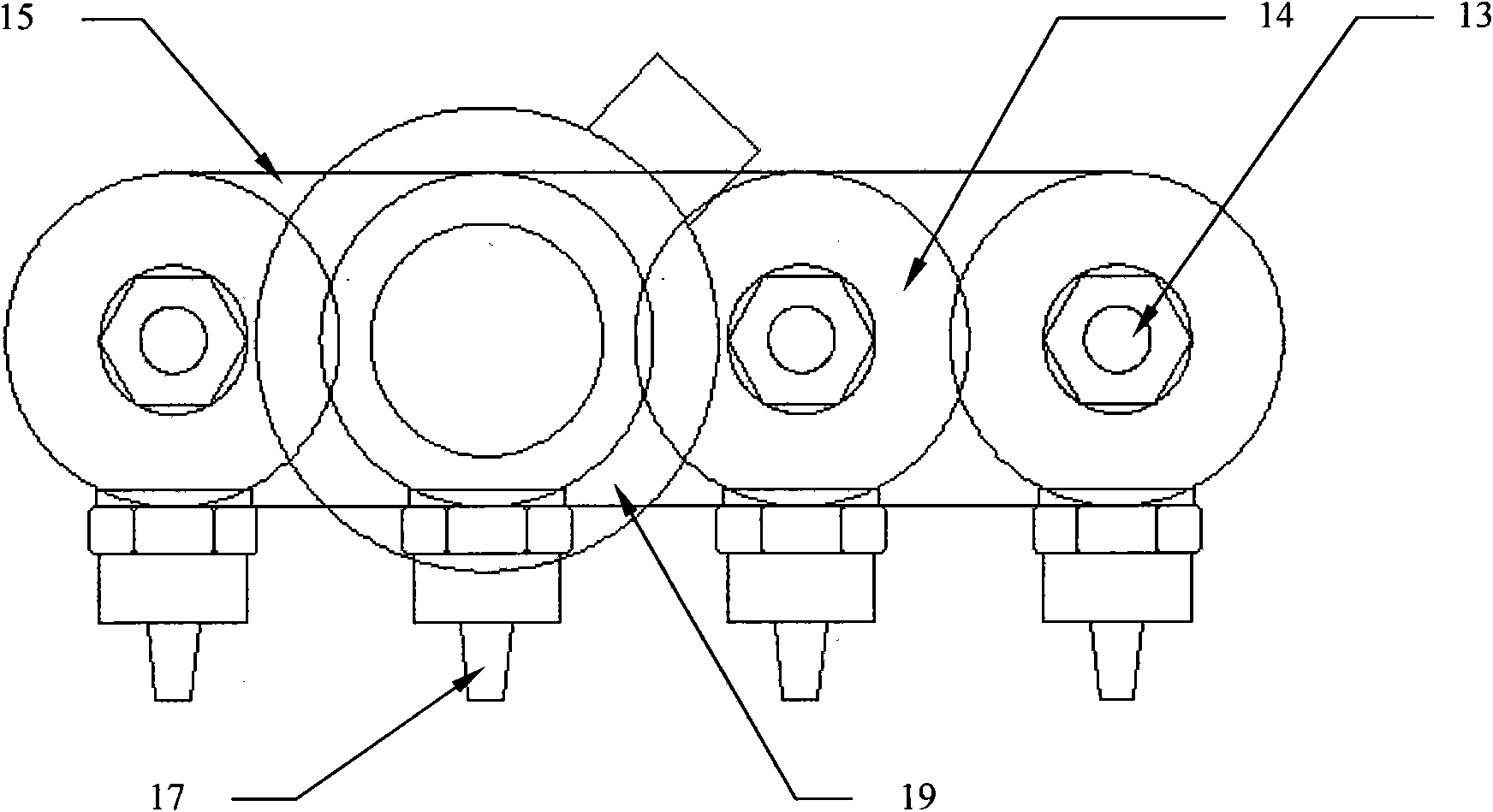
[0015] exist figure 1 A completed placement head is shown in . It takes the central axis of the cylinder body 1 as the axis, and sequentially installs the suction nozzle 4, the suction nozzle conduit 3, the suction nozzle buffer spring 6, the cylindrical slide iron 7, the slide iron return spring 9, the circlip 10, the cover 11, the through shaft 12. Gear 14, nut 13 and stepper motor 19, among which, there is a through hole 18 in the center of the cylindrical slide 7; the suction nozzle 4 slides in the suction nozzle duct 3, and the suction nozzle duct 3 and the cylindrical slide 7 are tightly fitted into one. The airflow enters from the suction nozzle 4 , enters the cylinder body 1 along the central through hole 18 of the cylindrical slide 7 , and is then drawn out from the suction nozzle 17 . The extended through shaft 12 of the stepping motor passes through the cover 11 on the cylinder body, and a metal pin is radially penetrated through the lower end of the through shaft...


PUM


Abstract

The invention relates to the technical field of chip mounters, in particular to a mounting structure of the chip mounter, and discloses a miniature array electromagnet mounting assembly which is assembled by a plurality of mounting heads capable of independently working in rows and arrays. A suction nozzle is moved up and down by the mounting head adopting an electromagnet; the direction positioning of all the suction nozzles of the mounting heads is controlled by a stepper motor; a shell, the lifting of the suction nozzle and a rotation mechanism are kept in a same axial lead; and the suctionnozzle is provided with a retractable damping device, thus effectively releasing the impact on a component, and simultaneously compensating the component mounting with unequal thickness. The mountingassembly is neatly integrated, has reasonable structure, simple and direct transmission link, small volume, light weight and effective response speed and facilitates flexible integration.

Description

【Technical field】 [0001] The invention relates to the field of placement machines for electronic assembly, in particular to the technical field of placement heads and suction nozzles of placement machines. 【Background technique】 [0002] With the advancement of electronic technology and the rapid development of electronic product manufacturing, the processing technology of mounting electronic components on printed circuit boards is increasingly adopted by many electronic manufacturers. To mount components with ever-shrinking dimensions on circuit boards, more use of electronic assembly and placement machines is required. In the high-speed operation state, the components are directly sucked from the component tape and accurately mounted on the circuit board. The placement head is a very critical component, and its response speed and running accuracy are similar to the placement head. Structure and weight have a direct relationship. [0003] In the existing technologies at h...

Claims


Application Information

Patent Timeline
Patent Type & Authority Applications(China)
IPC IPC(8): H05K13/04H05K3/30
Inventor 李建
Owner 李建
Why Eureka
Try Eureka