Straight wire PCB plane spiral coil primary current sensor

A planar spiral coil and current sensor technology, applied in the direction of inductors, fixed inductors, fixed signal inductors, etc., can solve the problems of anti-electromagnetic interference technology to be improved, low measurement accuracy, complex structure, etc.

Inactive Publication Date: 2010-03-24
周有庆
View PDF0 Cites 5 Cited by
  • Summary
  • Abstract
  • Description
  • Claims
  • Application Information

AI Technical Summary

Problems solved by technology

Due to the complex structure, high manufacturing process requirements, and anti-electromagnetic interference technology needs to be improved, the measurement accuracy of small current signals is not high
[0005] The Rogowski air-core coil PCB board type current sensor is to make the secondary coil on the circular PCB board, and the primary wire passes through the center of the PCB board vertically. There are also technical problems of the Rogowski air-core coil current sensor, and the measurement accuracy is lower and the anti-interference ability Not strong, still in the research stage
[0006] The helical tube hollow coil and PCB board hollow coil current sensor are the patented technology of the inventor of this patent. The primary coil is wound around a part of the secondary coil to form a spiral tube of various shapes with one or more turns, and the secondary coil is wound more than 4 times. The even number of spiral coils, the manufacturing process is complicated, and it is greatly affected by the electromotive force when passing a large current. The anti-interference effect of the secondary coil is better, and the accuracy is higher. Used as a primary current sensor for high-current electronic current transformers, currently in the development stage

Method used


Image

  • Straight wire PCB plane spiral coil primary current sensor
  • Straight wire PCB plane spiral coil primary current sensor
  • Straight wire PCB plane spiral coil primary current sensor

Examples


Embodiment Construction

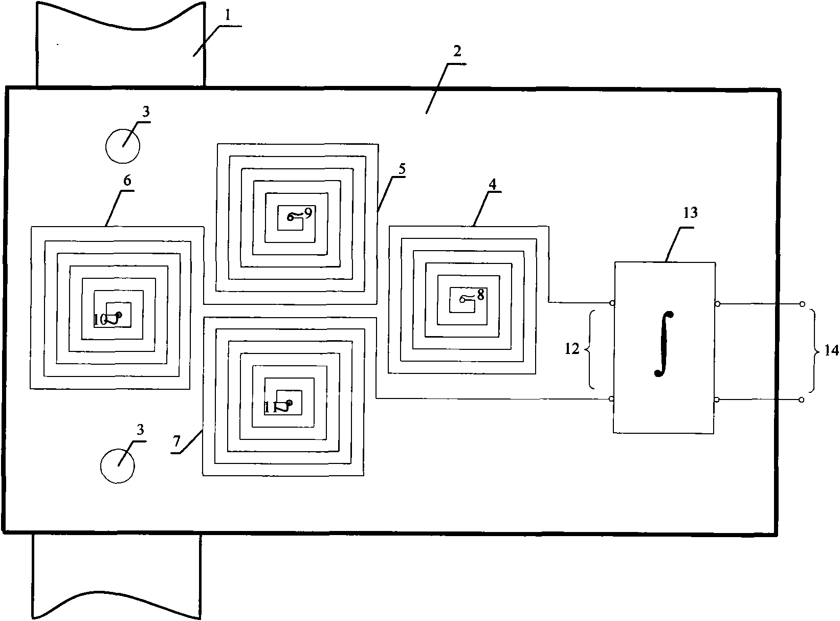
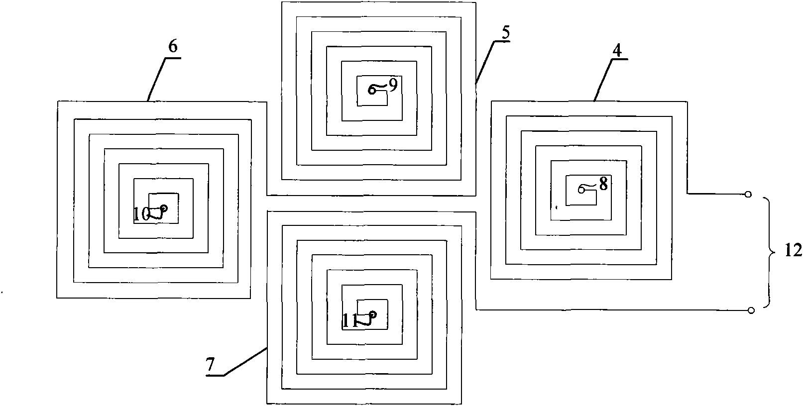
[0021] see figure 1 , in the figure 1 is the primary current straight wire, the cross section of the straight wire can be rectangular or circular, and both have a central axis; 2 is the PCB board printed with 4 planar spiral coils; 3 is the fastening between the PCB board and the primary straight wire Bolts; 4, 5, 6, and 7 are the same four planar spiral coils on the upper layer of the PCB; 8, 9, 10, and 11 are the magnetic center connection vias of the four planar spiral coils on the upper layer and the lower layer of the PCB; 12 is the PCB board The output terminal of the induced potential of the secondary coil; 13 is the integral amplifier; 14 is the output voltage terminal of the primary current sensor. If the cross-section of primary straight wire 1 is circular or rectangular, open a rectangular groove along the central axis. The four sides of the groove are required to be smooth and flat. In the groove, make the upper and lower edges of the straight wire groove coincide...


PUM


Abstract

The invention discloses a primary straight wire PCB plane spiral coil primary current sensor, a primary coil thereof is a straight wire with a circular or rectangular cross section, a secondary coil comprises two layers or an even number of layers of PCB circuit boards, the even number of same plane spiral coils above 4 are arranged on each layer of the PCB board, and the magnetic center of each spiral coil is arranged like an equilateral quadrilateral or an equilateral polygon. The adjacent coils in each layer are in sequential reverse-polarity series-connection, the spiral coils between thelayers are connected by through holes, the first end and the last end are used as output ends, and the spiral coils at the sides of the PCB boards are embedded in a cuneate groove of the central axisline of the straight wire or tightly bonded above, below or on two sides of the wire and fastened by using bolts. The primary straight wire PCB plane spiral coil primary current sensor can eliminate the interference of an external electromagnetic field, and the secondary coil can simultaneously sensitively respond to primary current in the straight wire and generate a secondary voltage signal which changes in direct proportion to the primary current, thereby having great linearity, measurement precision and anti-electromagnetic interference ability, and being applicable to being used as the current sensor for electronic current transformers of ultra-high voltage and various voltage levels therebelow.

Description

technical field [0001] The invention relates to a primary current sensor of an electronic current transformer, in particular to a primary current sensor of a straight lead PCB plane spiral coil. Background technique [0002] The prior art of primary current sensors of electronic current transformers includes magneto-optical effect type, Rogowski air-core coil type, Rogowski air-core coil PCB board type, spiral tube air-core coil type and PCB-type air-core coil current sensor. [0003] The magneto-optical effect current sensor uses the physical effects of optical materials, such as the Faraday magneto-optic effect, to measure current. Since the optical materials are greatly affected by factors such as ambient temperature and mechanical vibration, although there are prototypes running on the net at home and abroad, the operation The stability and reliability of the system are not high, and the price is expensive, and many key technologies such as phase angle measurement have n...

Claims


Application Information

Patent Timeline
Patent Type & Authority Applications(China)
IPC IPC(8): H01F38/28G01F15/18H01F17/00
Inventor 周有庆彭春燕龚伟王国华
Owner 周有庆
Why Eureka
Try Eureka