Tunnel magnetoresistive thin film and magnetic multilayer film formation apparatus

A technology of tunnel magnetoresistance and tunnel barrier layer is applied in the field of tunnel magnetoresistance film and magnetic multilayer film production device, and can solve the problem of extreme reduction of MR ratio and the like

Inactive Publication Date: 2010-03-31
CANON ANELVA CORP
View PDF2 Cites 14 Cited by
  • Summary
  • Abstract
  • Description
  • Claims
  • Application Information

AI Technical Summary

Problems solved by technology

[0004] In anticipation of the same effect, when NiFe is laminated on the CoFeB magnetization free layer in the conventional tunnel magnetoresistive film in which amorphous CoFeB is used as a ferromagnetic electrode and MgO is used as a tunnel barrier layer, there is a problem that the MR ratio is extremely lowered.

Method used


Image

  • Tunnel magnetoresistive thin film and magnetic multilayer film formation apparatus
  • Tunnel magnetoresistive thin film and magnetic multilayer film formation apparatus
  • Tunnel magnetoresistive thin film and magnetic multilayer film formation apparatus

Examples


Embodiment 1

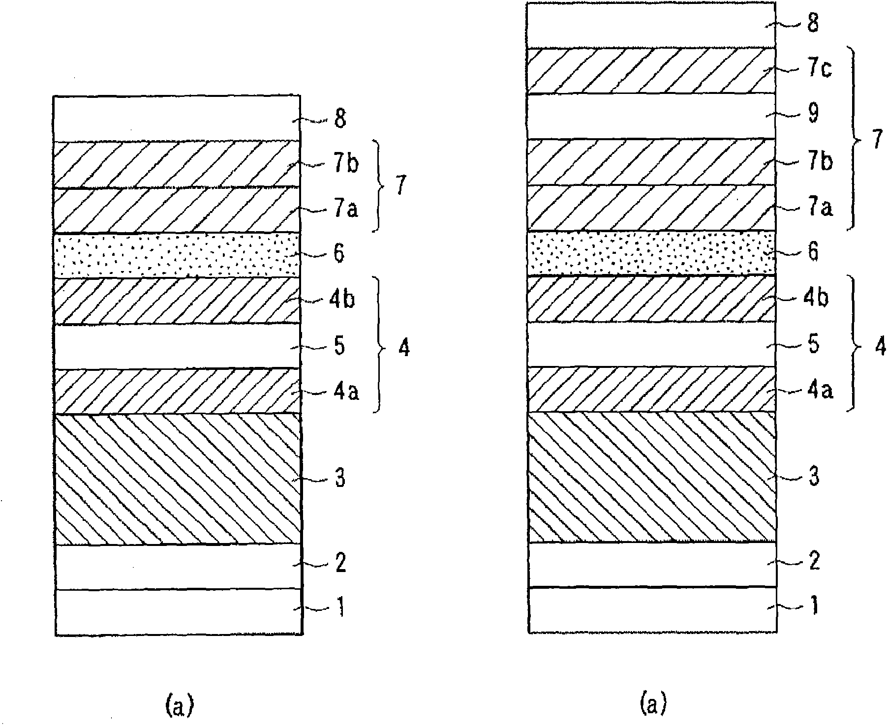
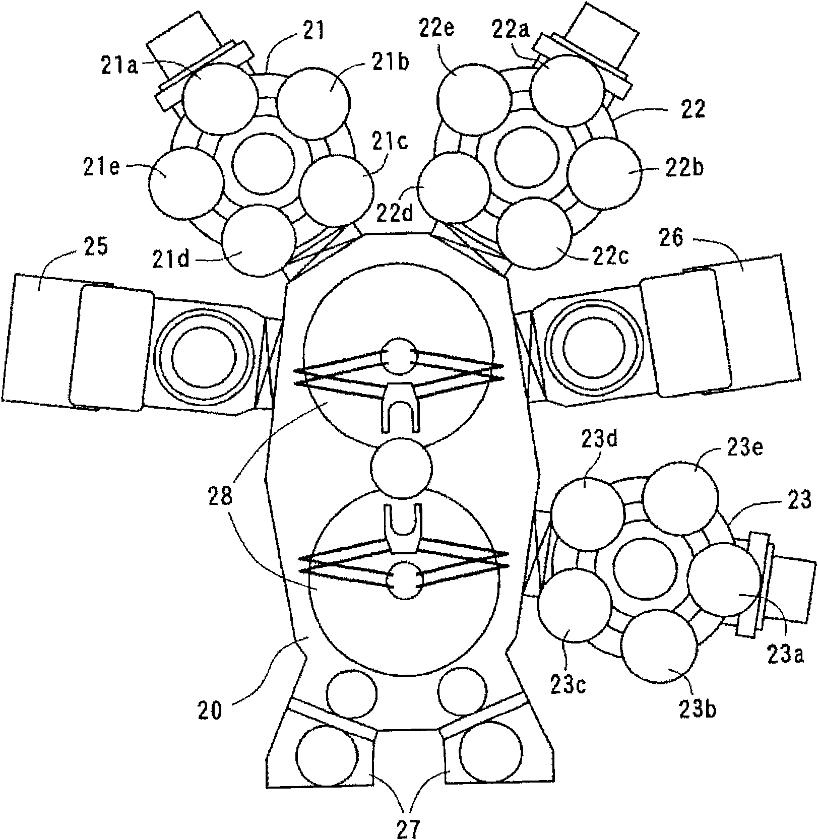
[0157] use figure 2 The device shown, making figure 1 A bottom-type spin-valve tunnel magnetoresistive thin film having a film structure shown in (a). In this example, the buffer layer 2 is Ta (10nm), the antiferromagnetic layer 3 is PtMn (15nm), and the magnetization pinned layer 4 is a laminated iron pinned layer composed of CoFe (2.5nm) / Ru (0.85nm) / CoFeB (3nm). layer, the tunnel barrier layer 6 is MgO (15nm). In addition, as the magnetization free layer 7 , CoNiFeB having a body-centered cubic structure is first formed into a film, and then NiFe with a face-centered cubic structure is formed into a film while maintaining the state at the time of film formation. As protective layer 8 , a stacked structure of Ta (10 nm) / Ru (7 nm) was used.

[0158] In addition, the first magnetization free layer 7a uses (Co 70 Fe 30 ) 96 B 4 , the second magnetization free layer 7b uses Ni with a face-centered cubic structure containing 83atomic% Ni 83 Fe 17 . In addition, as the ...

Embodiment 2

[0172] make figure 1 A bottom-type spin-valve tunnel magnetoresistive thin film having a film structure shown in (b). In this example, as the magnetization free layer 7, a Ru film (2nm) was laminated as the non-magnetic layer 9 for exchange coupling on the magnetization free layer of the CoNiFeB / NiFe film similar to the sample of the present invention in Example 1, and then a NiFe film was laminated. (3nm) as the magnetization free layer 7c, the same as the first embodiment.

[0173] The obtained magnetoresistive film had a high MR ratio and low magnetostriction as in Example 1, and also had improved heat resistance.

Embodiment 3

[0175] A bottom-type spin-valve tunnel magnetoresistive thin film using the sample of the present invention was produced in the same manner as in Example 1, except that the magnetization pinned layer 4 was made of amorphous CoFeB (3 nm).

[0176] The obtained magnetoresistive film had a high MR ratio and low magnetostriction as in Example 1, and also had improved heat resistance.


PUM

PropertyMeasurementUnit
thicknessaaaaaaaaaa

Abstract

This invention provides a tunnel magnetoresistive thin film which can simultaneously realize a high MR ratio and low magnetostriction. The tunnel magnetoresistive thin film comprises a magnetization fixed layer, a tunnel barrier layer, and a magnetization free layer. The tunnel barrier layer is a magnesium oxide film comprising magnesium oxide crystal grains having (001) orientation. The magnetization free layer has a laminated structure comprising a first magnetization free layer formed of an alloy having (001) orientation having a body centered cubic structure containing a Co atom, an Fe atom, and a B atom or a body centered cubic structure containing a Co atom, an Ni atom, an Fe atom, and a B atom, and a second magnetization free layer formed of an alloy having a face centered cubic structure containing an Fe atom and an Ni atom.

Description

technical field [0001] The invention relates to a sound-playing magnetic head of a disk drive device, a storage element of a magnetic random access memory, and a tunnel magnetoresistance film and a magnetic multilayer film manufacturing device used in a magnetic sensor. Background technique [0002] A tunnel magnetoresistive thin film using amorphous CoFeB as a ferromagnetic electrode and MgO with a NaCl structure as a tunnel barrier layer exhibits a large MR ratio (magnetoresistance change rate) of 200% or more at room temperature. Therefore, its application to a playback head of a magnetic disk drive, a storage element of a magnetic random access memory (MRAM), and a magnetic sensor is expected. The conventional tunnel magnetoresistive thin film using amorphous CoFeB as the ferromagnetic electrode and MgO as the tunnel barrier layer is a single layer of CoFeB with a positive and large magnetostriction in the magnetization free layer, so it is noisy when operating the devic...

Claims


Application Information

Patent Timeline
Patent Type & Authority Applications(China)
IPC IPC(8): H01L43/08G01R33/09G11B5/39H01F10/16H01F10/32H01L21/8246H01L27/105H01L43/10
CPCG11C11/16B82Y10/00H01L43/08H01F41/302G01R33/093G11B5/3906H01F10/3254H01L43/10B82Y40/00H01F10/16G11B5/3909H01L27/228B82Y25/00G01R33/098G11C11/15H01F10/3295G11C11/161Y10T428/1114Y10T428/1121H10B61/22H10N50/85H10N50/10H01F10/32G01R33/09H10B99/00
Inventor 恒川孝二永峰佳纪
Owner CANON ANELVA CORP
Why Eureka
Try Eureka