
Overlength tube cold-drawing machine

A technology of cold drawing machine and pipe, which is applied in the direction of metal drawing forming tools, metal wire drawing, manufacturing tools, etc. It can solve the problems of heavy weight of roller chains, uneven drawing speed, affecting surface quality, etc., and achieve stable operation , reduce mutual friction, improve the effect of surface quality

Active Publication Date: 2010-04-07
JIANGSU YINHUAN PRECISION STEEL TUBE CO LTD +1
View PDF0 Cites 11 Cited by
  • Summary
  • Abstract
  • Description
  • Claims
  • Application Information

AI Technical Summary

Problems solved by technology

When the existing cold drawing machine cold-draws the blank tube, the blank tube is firstly processed to make the end that can be clamped by the drawing car of the cold drawing machine. After annealing, the end of the blank tube is passed through the push tube Pass through the mold in the same way, and then use the clamping mechanism of the puller to clamp the end. The clamping mechanism generally adopts mechanical clamps without external force assistance. The mold is pulled out, and the head is removed at the end, and the useless end is cut off. The puller traction generally uses a roller chain to exert force. There is an instantaneous speed fluctuation in the chain transmission, which is likely to cause uneven drawing speed, thereby affecting the surface quality.
Due to the heavy weight of the roller chain, the cold drawing machine is relatively heavy and the operation is not flexible, especially for long pipes
In addition, the outer surface of the pipe needs to be pretreated when it is cold drawn, which also increases the processing cost

Method used


Image

  • Overlength tube cold-drawing machine
  • Overlength tube cold-drawing machine
  • Overlength tube cold-drawing machine

Examples


Embodiment 1

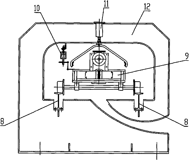
[0022] The structure of this embodiment is as figure 1 and figure 2 As shown, a super-long pipe cold drawing machine includes a drafting die 1 arranged on a head seat 2, a drawing trolley 9 that can move along a track 8 and a traction device connected to the drawing trolley 9. The traction device includes a The pulley block on the headstock 2, the motor 20 and the reducer 19 connected with the motor 20, the pulley block includes a fixed pulley 4, a movable pulley 5 and a fixed pulley 7; The adjusting lead screw 6 that the tension plays a regulating role, the thin steel wire rope 13 passes through one end of the fixed pulley 4 to connect the rear end of the drawing trolley 9, passes through the other end of the fixed pulley 7 and the small reel 15 located at the front end of the track 8 Connect, the front end of drawing trolley 9 is connected with the large reel 17 that is installed on small reel 15 sides by thick steel wire rope 14, and one end of small reel 15 is provided w...


PUM


Abstract

The invention relates to a tube cold-drawing processing device, in particular to an overlength tube cold-drawing machine. The invention comprises a drawing die arranged on a headstock, drawing trolley capable of moving along the rail and a dragging device connected with the drawing trolley; the dragging device comprises a pulley block arranged on a headstock, a motor and a retarder connected with the motor; the rail is provided with a clamping device; the pulley block is winded with a thin steel wire rope; one end of the thin steel wire rope is connected to the back end of the drawing trolley and the other end thereof is connected to a small winding drum arranged at the front end of rail; the front end of the drawing trolley is connected to a large winding drum arranged at one side of the small winding drum by a wide steel wire rope; the small winding drum is provided with a small gear; the large winding drum is provided with a large gear meshed with the small gear; and the large gear is connected with the retarder. The invention has the beneficial effects of simple and convenient operation, small error, time-saving, labor-saving, tube material-saving, good quality of tube drawing, and high processing efficiency.

Description

technical field [0001] The invention relates to a pipe cold drawing processing equipment, in particular to an ultra-long pipe cold drawing machine. Background technique [0002] The so-called cold drawing process refers to the direct cold drawing of large-diameter pipes into smaller-diameter pipes by using a draft die. The cold drawing machine is a mechanical device used to reduce the diameter and wall of the pipe or reduce the wall and expand the diameter. When the existing cold drawing machine cold-draws the blank tube, the blank tube is firstly processed to make the end that can be clamped by the drawing car of the cold drawing machine. After annealing, the end of the blank tube is passed through the push tube Pass through the mold in the same way, and then use the clamping mechanism of the puller to clamp the end. The clamping mechanism generally adopts mechanical clamps without external force assistance. The mold is pulled out, and the head is finally removed, and the ...

Claims


Application Information

Patent Timeline
Patent Type & Authority Applications(China)
IPC IPC(8): B21C1/22B21C3/02B21C3/00
Inventor 庄建新刘庆国
Owner JIANGSU YINHUAN PRECISION STEEL TUBE CO LTD
Learn More