
Governing system for constant temperature and constant humidity and integral constant temperature and humidity machine

A constant temperature and humidity machine, constant temperature and humidity technology, applied in the field of compressors, devices or systems, can solve the problems of insignificant effect of condensation heat, inability to achieve interval temperature, frequent change of unit operation, etc., to improve the adjustable range, Diversified functions, increase the effect of heating mode

Active Publication Date: 2010-04-07
GUANGDONG CHIGO AIR CONDITIONING
View PDF0 Cites 41 Cited by
  • Summary
  • Abstract
  • Description
  • Claims
  • Application Information

AI Technical Summary

Problems solved by technology

This control method, because the heat exchange air volume or water flow of the outdoor condenser has no obvious effect on the distribution of the condensation heat of the indoor condenser and the outdoor condenser, so the unit system cannot reach a certain temperature within the set temperature range under the temperature adjustment state. An interval temperature, this interval temperature is called the "temperature adjustment blind zone" of the system
If the set required temperature is just in the "temperature adjustment blind zone" of the system, it will inevitably cause frequent switching of unit operation, and the room temperature will also fluctuate greatly.

Method used


Image

  • Governing system for constant temperature and constant humidity and integral constant temperature and humidity machine
  • Governing system for constant temperature and constant humidity and integral constant temperature and humidity machine
  • Governing system for constant temperature and constant humidity and integral constant temperature and humidity machine

Examples


Embodiment Construction

[0036] The following will be described in conjunction with the accompanying drawings and specific embodiments.

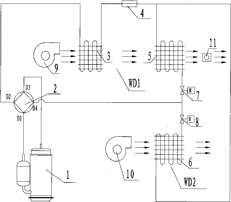
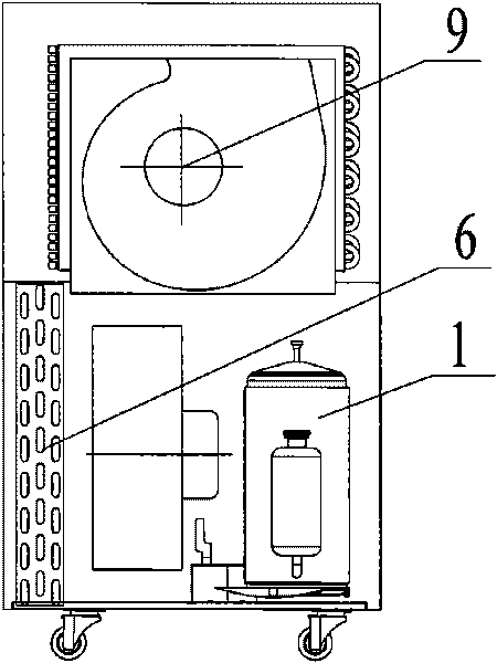
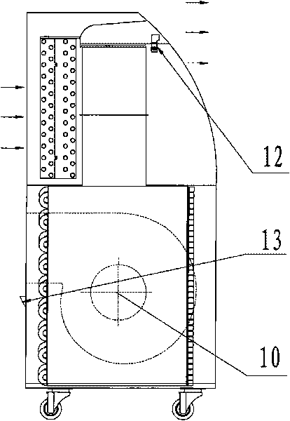
[0037] See figure 1 , which is a schematic diagram of the constant temperature and humidity regulation system of the present invention. The system is mainly composed of compressor 1, first heat exchanger 3, second heat exchanger 5, third heat exchanger 6, throttling device 4, first proportional valve 7, second proportional valve 8, four-way reversing Valve 2, humidifier 11, etc. are connected through refrigerant pipelines to form a refrigeration / heating cycle; wherein, the two branches of the first heat exchanger 3 and the second heat exchanger 5 are connected in parallel, and the second branch is installed on the two branches respectively. A proportional valve 7 and a second proportional valve 8 are used to control branch flow and on-off.

[0038] Specifically: the compressor 1, the first heat exchanger 3, the throttling device 4, and the second heat exchanger 5 ...


PUM


Abstract

The invention discloses a governing system for constant temperature and constant humidity, comprising a compressor, a first heat exchanger, a throttling device, a second heat exchanger, a third heat exchanger, an indoor air flue, an outdoor air flue, a wetting device, a four-way reversing valve, a first proportional valve and a second proportional valve, wherein the compressor, the first heat exchanger, the throttling device and the second heat exchanger are connected in series to form a circulation loop; the third heat exchanger is connected with the second heat exchanger in parallel; the indoor air flue is provided with an indoor fan, the first heat exchanger and the heat exchanger; the outdoor air flue is provided with an outdoor fan and the third heat exchanger; the wetting path of the wetting device is communicated with the indoor air flue; the first port of the four-way reversing valve is connected with the air suction port of the compressor, the second port is connected with the first heat exchanger, the third port is connected with the exhaust port of the compressor, and the four port is connected with the node of the second heat exchanger and the third heat exchanger; and the first proportional valve and the second proportional valve are respectively installed on a refrigerant pipeline on which the second heat exchanger and the third heat exchanger are arranged. The invention can enlarge the temperature adjusting range when a complete machine operates and avoid the temperature adjusting dead zone. The invention also provides an integral constant temperature and humidity machine.

Description

technical field [0001] The present invention relates to a compression machine, device or system with reversible cycle, specifically a constant temperature and humidity adjustment system and an integrated constant temperature and humidity machine. Background technique [0002] At present, most of the household integrated dehumidifiers sold on the market are ordinary heating types, and the indoor air supply temperature is higher than the operating environment temperature. In many dehumidification environments, especially in high temperature and high humidity conditions, excessively high air supply temperature It often brings discomfort to users; at the same time, ordinary integral dehumidifiers only have a dehumidification function, and blindly dehumidifying cannot effectively adjust the humidity of the environment and place. In order to meet the requirements of specific environment and place for specific temperature and humidity, and better meet the needs of human comfort, it...

Claims


Application Information

Patent Timeline
IPC IPC(8): F25B13/00F25B41/04F24F11/02F24F1/02F24F13/30F24F13/02
Inventor 成中坚胡轩恒王赛谢敏生
Owner GUANGDONG CHIGO AIR CONDITIONING
Learn More