Strong cooling heat dissipation method and device of high-power iron core reactor

A technology of heat dissipation device and reactor, applied in transformer/inductor cooling, transformer/inductor magnetic core and other directions, can solve the problems of short service life, difficult heat dissipation, temperature rise, etc., to improve service life, compact product structure, Craftsmanship effect

Active Publication Date: 2010-04-07
SHIDAI ELECTRIC FACTORY ZHUZHOU ELECTRIC LOCOMOTIVES INST MIN OF RAILWAYS
View PDF0 Cites 9 Cited by
  • Summary
  • Abstract
  • Description
  • Claims
  • Application Information

AI Technical Summary

Problems solved by technology

[0013] 1. It is difficult to dissipate heat, and the volume of the reactor increases under the same power condition;
[0014] 2. The temperature rises and the service life is short;
[0015] 3. Due to the use of air cooling, the reactor is noisy during operation;
[0016] 4. Due to the high power (above 300KVA), it is necessary to use high-grade magnetic materials and insulating materials, which increases the cost
[0017] High-power iron core reactor is a kind of electrical auxiliary equipment widely used in various high-power traction power systems. Because the power is high, the heat will be large, so for this type of reactor, an external water-cooled radiator is generally used for heat dissipation. , but at present this type of iron-core water-cooled heat dissipation reactor is used to set the cooling plate on the side of the reactor coil, and set some circulating cooling water pipes and cooling plates on the side of the reactor around the reactor coil and the iron core Connected, the heating of the reactor is taken out to the radiator for cooling through circulating cooling water. Although this cooling method has a certain effect, the effect is still not ideal, especially because the current cooling plates are located between the coils. Yes, so the (heat) heat of the iron core cannot be effectively taken away, so the (heat) heat of the iron core rises, so it is necessary to improve this

Method used


Image

  • Strong cooling heat dissipation method and device of high-power iron core reactor
  • Strong cooling heat dissipation method and device of high-power iron core reactor
  • Strong cooling heat dissipation method and device of high-power iron core reactor

Examples


Embodiment Construction

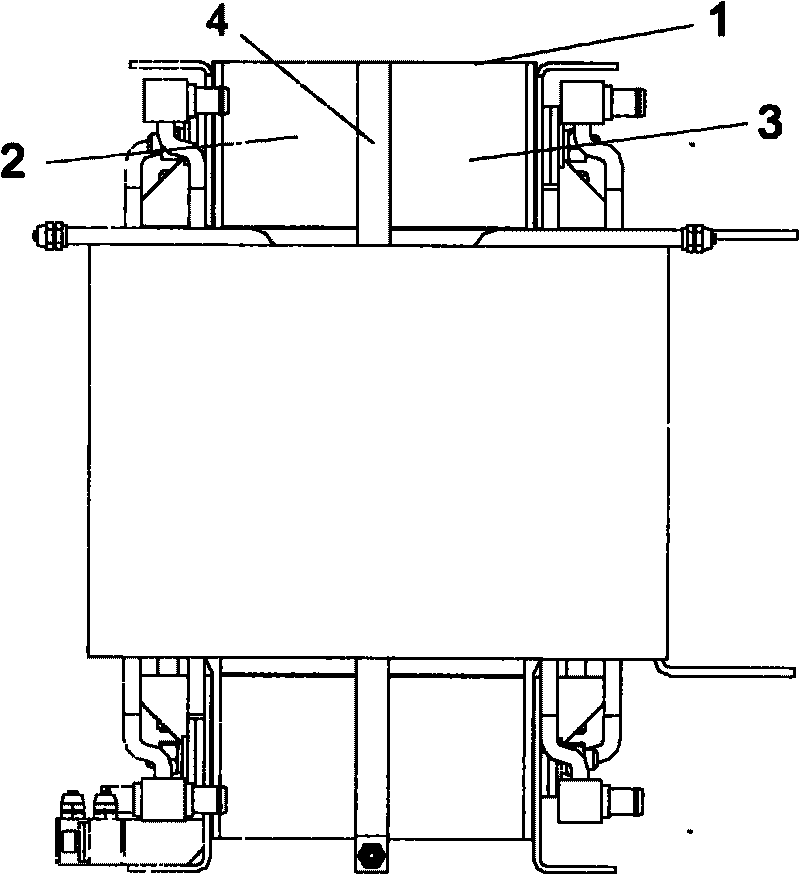
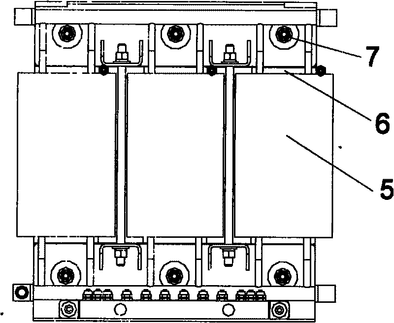
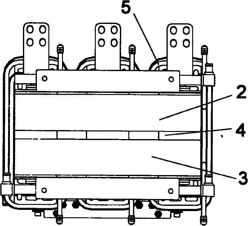
[0031] attached Figure 1-4 An embodiment of the present invention is given, and the present invention will be further described below in conjunction with the accompanying drawings.

[0032] It can be seen from the drawings that the present invention is a high-power iron-core reactor heat dissipation method, which is to disassemble the reactor iron core 1 along the longitudinal section of the iron core (that is, the direction in which the reactor coil and the coil are connected) Divided into two parts, namely the left iron core part 2 and the right iron core part 3, and a radiator (plate) 4 is added between the left iron core part 2 and the right iron core part 3. The two sides of the reactor (plate) 4 are closely attached to one side of the left iron core part 2 and the right iron core part 3 respectively, and the heat dissipation of the iron core part is passed through the radiator (plate) 4 in the middle of the reactor iron core of the two parts of the reactor. Go, cool th...


PUM


Abstract

The invention discloses a strong cooling heat dissipation method and device of a high-power iron core type reactor. The iron core of the reactor is divided into two parts between which a radiator is arranged, and the two divided irons cores are clung to two sides of the radiator, and the heat of the iron cores are taken out by the radiator arranged between the divided iron cores of the reactor so as to cool the iron cores. The radiator can be a plate-type water-cooling radiator or a pipe-type water-cooling radiator or a heat pipe radiator. The plate-type or pipe-type water-cooling radiator can be of a coiled pipe type radiator structure or of a groove-shaped cycling plate type radiator structure. In the invention, the iron core of the reactor is divided into two parts, and a heat dissipation device is arranged between the two parts, thereby effectively controlling the temperature of the iron core and playing a good role of heat dissipation for the reactor. Some special reactors have considerable heat value due to factors such as large current and environment factor when in work, and better heat dissipation effect can be achieved by adding various styles of reactors in the iron core or the side faces of the iron core and coils.

Description

technical field [0001] The invention relates to a heat dissipation method and a heat dissipation device for electric power equipment, especially a heat dissipation method and device for a high-power reactor. The international patent classification number is B61F05 / 02, which is mainly used for various high-power reactors or transformers. heat dissipation. Background technique [0002] The reactor is used to limit the current impact caused by the sudden change of the grid voltage and the operating overvoltage, smooth the peak pulse contained in the power supply voltage, or smooth the voltage defect generated when the bridge rectifier circuit commutates, it can prevent the interference from the grid, It can also reduce the pollution of the grid caused by the harmonic current generated by the rectifier unit. As a means of reactive power compensation, reactors are indispensable in power systems. And with the increase of transmission capacity, high-power reactors will emerge as ...

Claims


Application Information

Patent Timeline
Patent Type & Authority Applications(China)
IPC IPC(8): H01F27/08H01F27/16H01F27/24
Inventor 焦学军刘香平李纯董瑞洪
Owner SHIDAI ELECTRIC FACTORY ZHUZHOU ELECTRIC LOCOMOTIVES INST MIN OF RAILWAYS
Why Eureka
Try Eureka