Magnetic suspension electromotive force rotary wing flying saucer

一种磁悬浮、电动力的技术,应用在航空飞行器领域,能够解决飞碟碟体不可控反扭矩等问题,达到易于实现动力控制、重量轻、克服旋翼反扭矩的效果

Active Publication Date: 2010-04-14
BEIJING UNIV OF TECH
View PDF0 Cites 15 Cited by
  • Summary
  • Abstract
  • Description
  • Claims
  • Application Information

AI Technical Summary

Problems solved by technology

[0005] Similar to a general rotorcraft, a flying saucer rotor will generate a counter torque when it rotates, see patent CN 1114279A for details, there is a problem that the flying saucer body is subject to an uncontrollable counter torque

Method used


Image

  • Magnetic suspension electromotive force rotary wing flying saucer
  • Magnetic suspension electromotive force rotary wing flying saucer
  • Magnetic suspension electromotive force rotary wing flying saucer

Examples


Embodiment 1

[0022] Embodiment 1: Single-rotor maglev point power rotor flying saucer

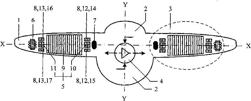
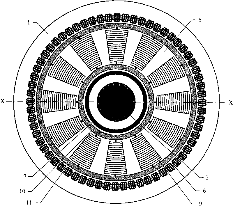
[0023] refer to figure 1 and figure 2 , the single-rotor maglev electric power rotor flying saucer includes: a dish shell 1, a disc cabin 2, a rotor system 3, and a control system 4, wherein the rotor system 3 is a magnetic levitation electric power rotor system, which consists of a magnetic levitation rotor wheel 5, an electric power ring 6, The magnetic levitation shaft 7 and the magnetic levitation guide rail 8 are composed; the electric power ring 6, the magnetic levitation shaft 7 and the magnetic levitation guide rail 8 are fixed on the disc shell 1; It is connected radially (X-X) between the magnetic levitation inner ring 10 and the magnetic levitation outer ring 11 to form an impeller; the magnetic levitation guide rail is divided into the magnetic levitation inner ring guide rail 12 and the magnetic levitation outer ring guide rail 13, and the magnetic levitation inner ring guide rail 12 is f...

Embodiment 2

[0028] Embodiment 2: Rotor wheel radial magnetic levitation structure

[0029] A magnetic levitation electric power rotor flying saucer, the magnetic levitation rotor wheel 5 is suspended on the magnetic levitation shaft 7 in the radial direction (X-X) according to the principle of magnetic levitation.

[0030] Such as Figure 5 Design the radial magnetic levitation structure of magnetic levitation rotor wheel 5 as shown, on the outer edge of the magnetic levitation inner ring 10 of the magnetic levitation rotor wheel 5 and the magnetic levitation shaft 7, paired magnets 22 are placed, and the magnet polarity of the magnetic levitation inner ring 10 is N pole facing inward, the S pole facing outward; the magnet polarity of the magnetic levitation shaft 7 is that the S pole faces inward, and the N pole faces outward. According to the principle that like magnets repel each other, the magnetic poles N on the outer edge of the magnetic levitation inner ring 10 and the magnetic po...

Embodiment 3

[0034] Embodiment 3: Rotor wheel axial magnetic levitation structure

[0035] A magnetic levitation electric power rotor flying saucer, the magnetic levitation rotor wheel 5 is suspended on the magnetic levitation guide rail 8 in the axial direction (Y-Y) according to the principle of magnetic levitation, that is: the magnetic levitation inner ring 10 is suspended in the upper guide rail groove 14 of the inner ring and the lower guide rail groove 15 of the inner ring Between them, the magnetic levitation outer ring 11 is suspended between the upper guide rail groove 16 of the outer ring and the lower guide rail groove 17 of the outer ring.

[0036] Such as Figure 6 The axial magnetic levitation structure of the design magnetic levitation rotor wheel 5 shown in the figure makes the magnet polarity of the magnetic levitation inner ring 10 and the magnetic levitation outer ring 11 be, the N pole is on the top, and the S pole is on the bottom; the inner ring upper guide rail groo...


PUM


Abstract

The invention discloses a magnetic suspension electromotive force rotary wing flying saucer, which comprises a saucer shell, a saucer cabin, a rotary wing system and a control system. The flying saucer is characterized in that the rotary wing system is a magnetic suspension electromotive force rotary wing system comprising magnetic suspension rotary wing wheels, an electromotive force ring, a magnetic suspension shaft and a magnetic suspension guide rail, and self-supporting electromagnetic power pushes rotary wings to rotate; the rotary wings and a motive power system thereof are integrated into a whole, thereby being favorable for reducing volume, lightening weight, improving motive power conversion efficiency and easily controlling rotation movement. The rotary wing wheels are suspended on the magnetic suspension shaft in a radical direction and suspended on the magnetic suspension guide rail in an axial direction, thereby effectively preventing contact or friction between the rotary wing wheels and the inner portion of the saucer shell during the rotation of the rotary wing wheels. The improvement of the invention further includes that two sets of magnetic suspension electromotive force rotary wing systems are superposed and mounted coaxially up and down inside the saucer shell; two sets of magnetic suspension rotary wing systems are imbedded and mounted inside and outsidecoaxially inside the saucer shell, thereby overcoming reactive torque formed during the rotation of the rotary wings and realizing automatic control for self-rotating angles and self-rotating angularvelocity.

Description

technical field [0001] The invention belongs to the field of aviation aircraft, and in particular relates to a magnetic levitation electric power rotor flying saucer. technical background [0002] The lift and thrust of the rotorcraft are formed by the high-speed rotating rotor, and the power of the rotor rotation comes from the engine. Existing rotary-wing aircrafts include various rotary-wing helicopters, and its rotor and engine are two separate and independent systems, which are connected together by a transmission mechanism. [0003] Compared with the general rotorcraft, the particularity of the rotorcraft is that the rotor system and its power system of the rotorcraft need to be installed in the disc shell. The internal space of the disc shell is limited, which limits the structure and layout of the rotor system and its power system. Therefore, how to make full use of the limited space inside the disc shell, design a compact structure, reasonable layout, light weight...

Claims


Application Information

Patent Timeline
Patent Type & Authority Applications(China)
IPC IPC(8): B64C39/06B64D27/02B64D27/26
CPCY02T50/62B64D27/24B64C2201/027B64C2201/127B64C2201/108B64C2201/042B64C27/20Y02T50/60Y02T50/40B64U10/13B64U30/20B64U50/19B64U2101/30
Inventor 阮晓钢侯旭阳
Owner BEIJING UNIV OF TECH
Why Eureka
Try Eureka