Memory alloy calibrating lock and method for realizing locking and unlocking of satellite calibrating device by using same

A memory alloy and memory alloy spring technology, applied in the field of aerospace optical remote sensors, can solve the problems of reduced reliability, heavy weight, large volume, etc., and achieve the effect of less parts, light weight and small volume

Inactive Publication Date: 2010-04-14
BEIJING RES INST OF SPATIAL MECHANICAL & ELECTRICAL TECH
View PDF0 Cites 7 Cited by
  • Summary
  • Abstract
  • Description
  • Claims
  • Application Information

AI Technical Summary

Problems solved by technology

These two structural forms are large in size and heavy in weight, and require the use

Method used


Image

  • Memory alloy calibrating lock and method for realizing locking and unlocking of satellite calibrating device by using same
  • Memory alloy calibrating lock and method for realizing locking and unlocking of satellite calibrating device by using same
  • Memory alloy calibrating lock and method for realizing locking and unlocking of satellite calibrating device by using same

Examples


Embodiment Construction

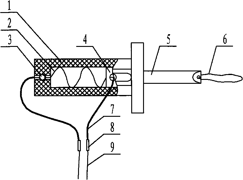
[0029] Such as image 3 As shown, the memory alloy calibration lock of the present invention includes a sleeve 1, a memory alloy spring 2, a screw 3, a limit block 4, a metal shaft 5, a soft rope 6, a heat shrinkable sleeve 7, a crimping terminal 8, and a wire 9. The memory alloy spring 2 and the limit block 4 are located inside the sleeve 1 , a part of the metal shaft 5 is inside the sleeve 1 , and a part is outside the sleeve 1 . One end of the memory alloy spring 2 is led out from the axial through hole at the bottom of the sleeve 1 and is screwed in and compressed by the screw 3 from the vertical direction. The other end of the alloy spring 2 extends into the axial through hole of the limit block 4, turns 90° and passes through the side and the side opening of the sleeve 1, and installs the screw 3 in the vertical position of the axial through hole of the limit block 4 Press and fix the memory alloy wire; add the memory alloy wire outside the sleeve 1 to the heat shrinkab...


PUM

PropertyMeasurementUnit
Diameteraaaaaaaaaa

Abstract

The invention discloses a memory alloy calibrating lock, wherein one end of a memory alloy spring extends from a small hole at the bottom of a sleeve and is fixed by a screw at one side, and the other end is fixed on a limiting block and extends out of the side of the sleeve. A memory alloy wire outside the sleeve is provided with a heat-shrinkable sleeve and connected with leads of a control circuit through a pressure welding way. One end of a metal shaft is fixed on the limiting block and the other end is connected with a soft rope. The calibrating lock has the characteristics of small volume, light weight, simple structure and high reliability. When the calibrating device realizes the locking or the unlocking by the memory alloy calibrating lock, the assembly is fixed on a base of the calibrating device through the bolt. The soft rope is straightened for certain time, the metal shaft extends into a locking hole of a swinging rod of the calibrating device, and the spring has no restoring force to complete the locking. The control circuit electrifies the memory alloy spring when unlocking is needed, the spring restores the original shape of the memory after the phase-transition temperature is achieved, and the metal shaft is driven to retract towards the inner side of the sleeve so as to disengage from the locking hole of the swinging rod to realize the unlocking.

Description

technical field [0001] The invention belongs to the technical field of aerospace optical remote sensors, and relates to a calibration lock made of a shape memory alloy and a method for realizing locking and unlocking of a calibration device of an infrared optical remote sensing camera by using the same. Background technique [0002] The calibration device is a device that makes the surface source blackbody block the optical path during calibration and exit the optical path when it is not calibrated through the driving mechanism. By controlling the blackbody to complete the cut-in and cut-out of the optical path according to the predetermined sequence and instructions, the blackbody on the star is realized. Calibration function. The calibration device contains moving parts, which are required to be locked during launch and unlocked once in orbit. [0003] The calibration device looks like figure 1 As shown, by the base 10, the counterweight 11, the electromagnet 12, the cal...

Claims


Application Information

Patent Timeline
IPC IPC(8): G01S7/497
Inventor 赵艳华翟广泉行麦玲
Owner BEIJING RES INST OF SPATIAL MECHANICAL & ELECTRICAL TECH
Why Eureka
Try Eureka