
Punching structure of NC turret punch machine application switch reluctance servo motor

A technology of CNC turret punch press and switched reluctance, which is applied in punching machines, mechanical energy control, presses, etc., can solve the problems of environmental pollution, high power consumption, and high use and maintenance costs, and can save cooling systems and reduce noise. , the effect of simple structure

Inactive Publication Date: 2010-04-21
JIANGSU JINFANGYUAN CNC MACHINE CO LTD
View PDF0 Cites 6 Cited by
  • Summary
  • Abstract
  • Description
  • Claims
  • Application Information

AI Technical Summary

Problems solved by technology

However, the shortcomings of the hydraulic system are also very obvious. First of all, it consumes a lot of power. The oil pump motor of the hydraulic station is always in a high-speed operation state. In view of the leakage characteristics of the oil pump itself, to maintain an accurate position, it must be kept running to keep the pressure constant.
In addition, the hydraulic system has high requirements on the particles of hydraulic oil, requiring regular replacement of hydraulic oil and working filter elements every year, so the user's use and maintenance costs are high
There is also the discharge of waste oil, which is also polluting the environment.

Method used


Image

  • Punching structure of NC turret punch machine application switch reluctance servo motor
  • Punching structure of NC turret punch machine application switch reluctance servo motor
  • Punching structure of NC turret punch machine application switch reluctance servo motor

Examples


Embodiment 1

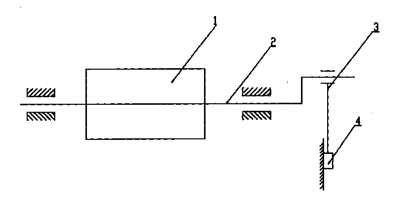
[0023] Such as figure 1 Shown: a stamping structure of a CNC turret punching machine using a switched reluctance servo motor, including a switched reluctance servo motor 1, a crankshaft 2, a connecting rod 3 and a slider 4, the switched reluctance servo motor 1 is directly installed on the crankshaft At one end of 2, the crankshaft 2 directly driven by the switched reluctance servo motor 1 is connected to the connecting rod 3, and the connecting rod 3 is connected to the slider 4 to form a planar connecting rod mechanism.

[0024] The switched reluctance servo motor 1 has a double-salient stator and rotor structure, and the rotor is made of laminated silicon steel sheets without windings and permanent magnets, allowing a relatively high temperature rise.

[0025] The rotation angle of the crankshaft 2 is controlled in a semi-closed loop by the switch reluctance servo motor 1 with its own encoder feedback. The swing angle or rotation of the crankshaft 2 is determined according ...

Embodiment 2

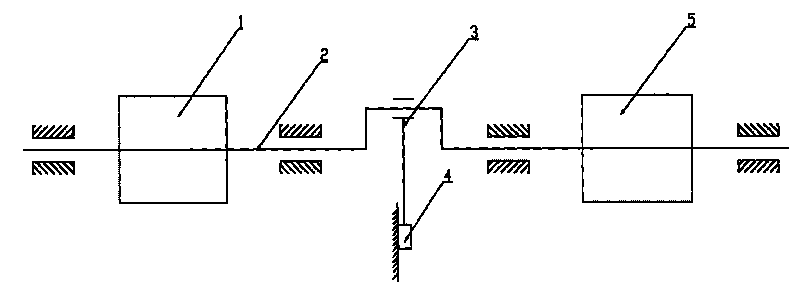
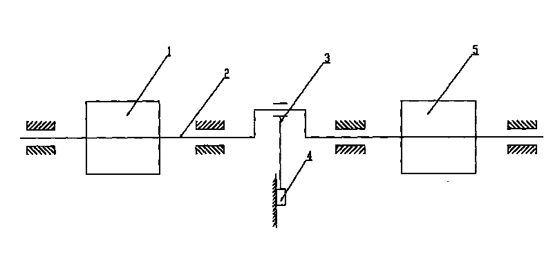
[0027] Such as figure 2 Shown: a stamping structure of a CNC turret punching machine using a switched reluctance servo motor, including a switched reluctance servo motor 1, a crankshaft 2, a connecting rod 3 and a slider 4, the switched reluctance servo motors 1 are a pair, They are directly installed at both ends of the crankshaft 2, and the crankshaft 2 is synchronously driven by the switched reluctance servo motor 1. The crankshaft 2 is connected with the connecting rod 3, and the connecting rod 3 is connected with the slider 4 to form a planar linkage mechanism.

[0028] The switched reluctance servo motor 1 has a double-salient stator and rotor structure, and the rotor is made of laminated silicon steel sheets without windings and permanent magnets, allowing a relatively high temperature rise.

[0029] The rotation angle of the crankshaft 2 is semi-closed-loop controlled by the encoder of the active motor in the pair of switched reluctance servo motors 1, and the slave m...


PUM


Abstract

The invention provides an energy-saving, environmentally-friendly, efficient and maintenance-free punching structure of an NC turret punch machine application switch reluctance servo motor, comprising a switch reluctance servo motor, a crank shaft, a connecting rod and a slide block, wherein the switch reluctance servo motor is connected with the crank shaft, the crank shaft which is directly driven by the switch reluctance servo motor is connected with the connecting rod, and the connecting rod is connected with the slide block so as to form a planar linkage. The switch reluctance servo motor can be directly arranged at one end of the crank shaft in the number of one and can be respectively directly arranged at both ends of the crank in the number of two, and the crank shaft is synchronously driven by the switch reluctance servo motor.

Description

technical field [0001] The invention relates to a structure of a numerically controlled turret punch press, in particular to a stamping structure using a switched reluctance servo motor for a numerically controlled turret punch. Background technique [0002] The stamping main transmission part of the traditional CNC turret punch press has two structures: mechanical and hydraulic. [0003] The mechanical type is that the AC asynchronous motor drives the flywheel to rotate at a high speed, and the crankshaft mechanism of the mechanical main drive is driven by the combination of the clutch to complete the stamping action during stamping. When the stamping action is completed, the clutch is disengaged, but the AC asynchronous motor does not stop, and is always in a high-speed running state. Moreover, the upper dead center and the lower dead center of stamping cannot be changed, which is not conducive to the forming or embossing of plates and other processes. Due to the limitat...

Claims


Application Information

Patent Timeline
IPC IPC(8): B30B1/14B30B15/14H02K7/10B21D28/26B21D22/02
CPCB30B1/266
Inventor 吴宏祥叶敬春李强王雪
Owner JIANGSU JINFANGYUAN CNC MACHINE CO LTD
Learn More