Radial magnetic bearing of low-power consumption inner rotor of permanent-magnetic up-attracting and down-repelling structure

A low-power, inner-rotor technology, used in bearings, shafts and bearings, mechanical equipment, etc., can solve the problems of high current consumption, difficult installation, complex control, etc., to reduce iron loss, low loss, and eliminate magnetic loss. Effect

Inactive Publication Date: 2010-04-21
SHANDONG UNIV OF SCI & TECH
View PDF0 Cites 20 Cited by
  • Summary
  • Abstract
  • Description
  • Claims
  • Application Information

AI Technical Summary

Problems solved by technology

At present, pure passive magnetic suspension bearings are difficult to install. Pure active magnetic suspension bearings consume a lot of current and consume a lot of power. The most notable feature of passive and active magnetic suspension bearings is that they use permanent magnets to generate bias magnetic fields. , using the electromagnetic field to adjust the balance position of the rotor, which reduces the excitation current and power loss to a certain extent; however, hybrid magnetic suspension bearings generally place permanent magnets on the basis of ordinary radial electromagnetic bearings, so that the permanent magnets The magnetic circuit and the electromagnetic magnetic circuit are independent of each other, and there is a certain cross area, so that the electromagnetic field generated by the current in the exciting coil will increase the magnetic flux density of the air gap between the rotor and the stator on one side and decrease on the other side, thus The magnetic field force that adjusts the balance position of the rotor is generated, but this force is attractive in four directions and cannot counteract the gravity of the rotor itself, and the magnetic flux on the side where the magnetic flux density decreases in the air gap between the rotor and the stator does not may be completely reduced to zero, and this non-zero magnetic field will create resistance to adjust the balance
Due to the above defects, the existing permanent magnet bias bearings have the disadvantages of gravity interference, slightly larger power consumption, and complicated control.

Method used


Image

  • Radial magnetic bearing of low-power consumption inner rotor of permanent-magnetic up-attracting and down-repelling structure
  • Radial magnetic bearing of low-power consumption inner rotor of permanent-magnetic up-attracting and down-repelling structure
  • Radial magnetic bearing of low-power consumption inner rotor of permanent-magnetic up-attracting and down-repelling structure

Examples


Embodiment Construction

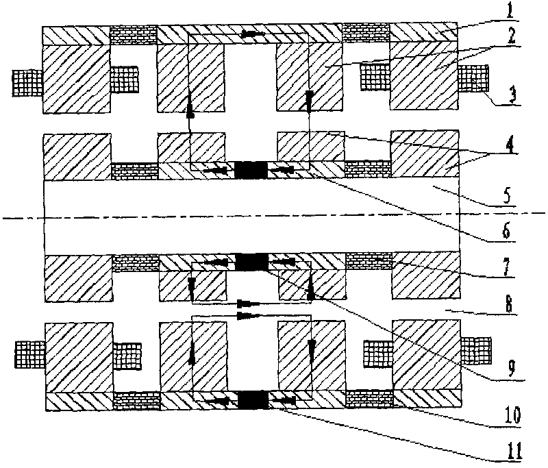
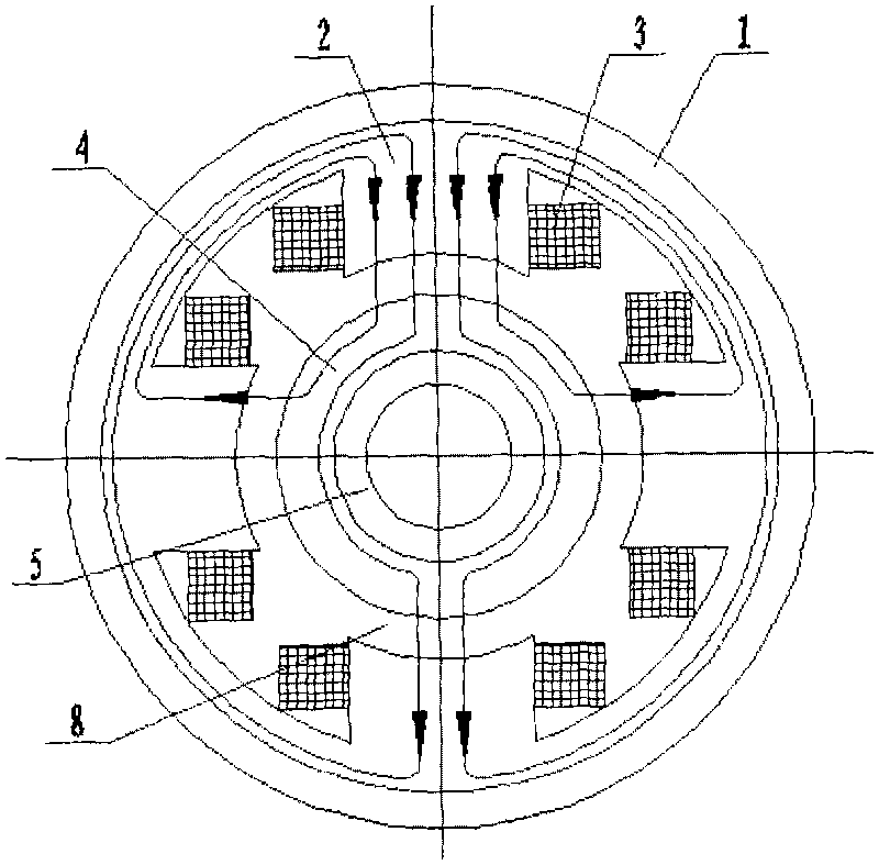
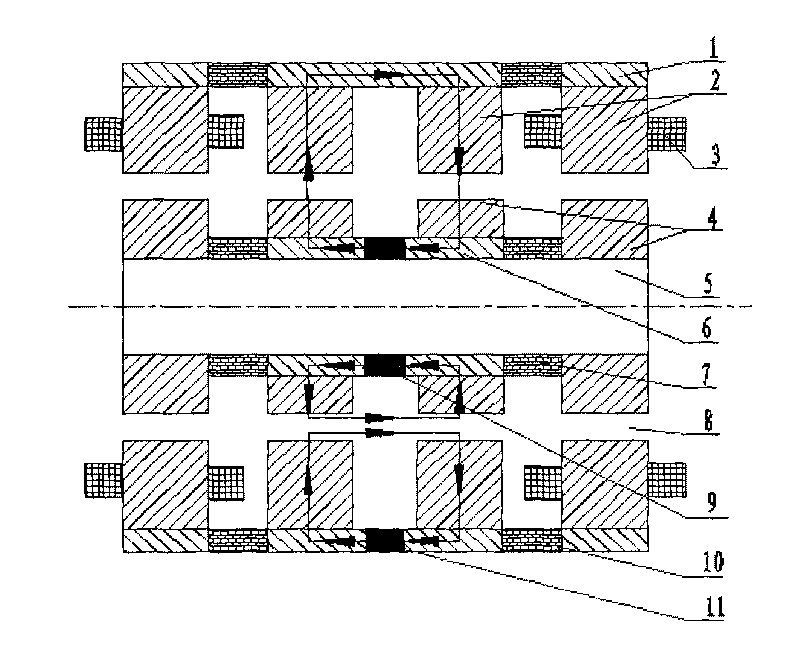
[0009] Such as figure 1 and figure 2 As shown, it is the basic implementation form of the technical solution of the present invention, which consists of 2 outer magnetic rings 1, 3 outer magnetic half rings 1, 1 permanent magnetic ring 9, 1 permanent magnetic half ring 11, and 12 stators Iron core 2, 8 excitation coils 3, 2 inner magnetic rings 6, 4 rotor cores 4, 12 air gaps 8, 2 inner magnetic isolation rings 7, and 2 outer magnetic isolation rings 9. Each stator core 2 includes 4 electromagnetic poles in the positive and negative directions of the X-axis and Y-axis, and 2 permanent magnet poles in the positive and negative directions of the Y-axis. The stator cores at the left and right ends form 8 electromagnetic poles and 4 A permanent magnetic pole, an excitation coil 3 is wound on the electromagnetic pole, an outer magnetic ring 1 is outside the stator core 2, and the outer magnetic ring 1 is connected with the outer magnetic ring 10, and between the two outer magneti...


PUM


Abstract

The invention discloses a radial magnetic bearing of a low-power consumption inner rotor of a permanent-magnetic up-attracting and down-repelling structure, which consists of an outer magnetic conduction ring, an outer magnetic insulation ring, a stator core, a magnet exciting coil, an inner permanent-magnetic ring, a rotor core, an inner magnetic insulation ring, an inner magnetic conduction ring, an outer permanent-magnetic half ring, an air gap and a rotating shaft. The stator core is provided with eight electromagnetic poles and four permanent-magnetic poles in the positive and negative directions of an X axis and a Y axis, the outer magnetic insulation ring is arranged between a permanent-magnetic core and an electromagnetic core on a stator, and the outer permanent-magnetic half ring is clamped in the middle of two permanent-magnetic cores in the negative direction of the Y axis of the stator through the outer magnetic conduction ring. The air gap is reserved between the stator core and the rotor core, the inner magnetic insulation ring is arranged between a permanent-magnetic core ring and an electromagnetic core ring on a rotor, the inner magnetic conduction ring is arranged between the permanent-magnetic core rings, and the inner permanent-magnetic ring is clamped in the middle of the inner magnetic conduction ring. The radial magnetic bearing of the low-power consumption inner rotor has the advantages of low power consumption, simple control, convenient manufacture and the like, and can be used as a non-contact support component of rotary equipment such as wind driven generators, electro motors, molecular pumps, high-speed bearings, machine tools and the like.

Description

Technical field [0001] The patent of the invention relates to a non-contact magnetic suspension bearing, especially a low-power inner rotor radial magnetic bearing with a permanent magnet up-suction and down-repulsion structure, which can replace the current mechanical bearing and can be used as a wind power generator, motor, molecular pump , High-speed bearings, non-contact supporting parts of rotating equipment such as machine tools. Background technique [0002] Because the magnetic suspension bearing has the advantages of no contact, no lubrication, long life and low noise, it is of great significance in the fields that require friction reduction and high-speed operation. The application of magnetic suspension bearings in wind power generator systems removes the original mechanical bearings and The speed-up gear can reduce the minimum starting wind speed to about 1.5m / s, and increase the average annual power generation time by 30%-50%. At present, pure passive magnetic ...

Claims


Application Information

Patent Timeline
Patent Type & Authority Applications(China)
IPC IPC(8): F16C32/04
Inventor 肖林京孙传余李鹏高峰
Owner SHANDONG UNIV OF SCI & TECH
Why Eureka
Try Eureka